Waste-to-Energy Plant Model Making: Design, Components and Working
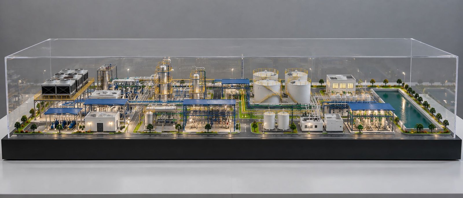
Waste-to-Energy Plant Model Making shows how a plant receives waste, processes it and recovers useful energy. A physical scale model can show the complete plant layout in a clear and attractive way. Moreover, unlike a simple building model, this type of model includes industrial equipment, waste receiving areas, conveyors, combustion systems, boilers, pipes, pollution-control equipment, turbines, cooling systems and electrical sections.
A good physical model should look like a small industrial plant. Therefore, it should have a strong rectangular base, realistic buildings and correctly placed equipment. Small pipes, platforms, ladders, tanks, roads, safety railings and landscaping can add more detail. In addition, transparent sections can help viewers see important parts inside the plant.
The main purpose of a Waste-to-Energy Plant Model is to explain the complete process through a three-dimensional display. As a result, architects, engineers, consultants, project developers, students and industrial teams can use the model for presentations, exhibitions, project discussions and educational demonstrations.
What Is a Waste-to-Energy Plant?
A Waste-to-Energy plant processes suitable waste and recovers energy from it. First, the plant may prepare and treat the waste before thermal processing. Next, the process produces heat that can generate steam. Then, the steam can drive a turbine connected to an electrical generator.
A physical Waste-to-Energy Plant Model shows this complete arrangement at a smaller scale. For example, the model can show how waste moves from the receiving area to the processing section and then toward the energy-generation section.
The model can include a waste receiving building, waste storage pit, overhead crane, conveyor system, furnace or boiler section, steam and gas pipes, pollution-control equipment, turbine hall, electrical equipment and chimney.
Therefore, the model does more than show the outside of the plant. It also explains how different areas connect with each other. In this way, viewers can understand how waste, heat, steam and energy move through the facility.
Importance of Waste-to-Energy Plant Model Making
Industrial plants can look complex in normal drawings. A 2D plan can show equipment locations. However, it may not clearly show height, depth and the relationship between different plant sections.
A physical model presents the plant in three dimensions. As a result, viewers can understand the position of buildings, machinery, storage areas and service systems more easily.
Waste-to-Energy Plant Model Making works well for projects with many industrial sections. Moreover, a single physical model can bring these different areas together in one clear presentation.
Engineers can also use the model during project meetings. For example, they can point to different plant areas while explaining the general arrangement. Similarly, educational institutions can use a simplified model to explain waste processing and energy recovery.
Furthermore, the model can work as an exhibition display. Proper lighting, landscaping and industrial details can help visitors understand the facility from different viewing angles.
Waste-to-Energy Plant Model Design
The overall design forms the base of Waste-to-Energy Plant Model Making. Therefore, the model should follow a clear arrangement similar to a real industrial site.
A rectangular base works well because it provides enough space for buildings, roads, equipment and landscaping. In addition, a raised border can protect the model and give the base a clean finish.
First, the designer can arrange the major sections according to the plant process. The waste receiving area can sit near the entrance. Next, the storage pit can connect with the crane and feeding system. The main processing building can occupy the central area.
After that, the boiler, gas-treatment equipment, chimney and power-generation sections can surround the main processing building. Meanwhile, the electrical area can sit separately with transformers and switchgear.
Finally, roads should connect the entrance with the waste receiving building and service areas. In addition, small vehicles can help viewers understand the model scale.
Waste Receiving Area in the Physical Model
The waste receiving area forms an important part of the Waste-to-Energy Plant Model because waste enters the facility through this section.
A large receiving building can use acrylic, PVC sheet, MDF, foam board or similar model-making materials. For example, large openings at the front can allow miniature waste collection trucks to enter the building.
Inside the building, the designer can create a storage pit. The pit should sit below the surrounding floor level. As a result, the difference in height can give the model a more realistic industrial appearance.
Miniature waste trucks can stand outside or inside the receiving area. Moreover, different truck sizes can create a more natural scene.
Transparent acrylic walls can keep the internal process visible. Similarly, removable sections can give viewers access to the inside of the model.
Waste Storage Pit and Crane Model
The waste storage pit creates one of the most recognizable areas in the plant. Therefore, a physical model can highlight it as a large rectangular recessed section.
An overhead crane can sit above the pit. For example, the crane can include a horizontal beam, trolley, lifting cable and grab bucket.
The grab bucket can hang above the waste material. In this way, the model can show how the crane moves waste from the storage area toward the feeding system.
For a working model, a small low-voltage motor can move the crane along its track. In addition, another small mechanism can raise and lower the grab bucket.
As a result, this feature makes the Waste-to-Energy Plant Model more interactive. It also helps viewers understand the material-handling process.
Conveyor System in Waste-to-Energy Plant Model
Conveyors connect different processing areas. Therefore, a physical model should show the conveyor with a realistic frame, belt and support structure.
The maker can use a thin rubber sheet or another flexible material for the belt. In addition, small rollers can run along the sides.
The conveyor should connect correctly with the waste feeding area. At the same time, its height and angle should match the nearby equipment.
Yellow or metallic railings can surround raised conveyor sections. Moreover, small platforms and stairs can add more industrial detail.
For a working model, a small low-speed motor can move the conveyor belt. As a result, viewers can see how material moves through the plant.
Boiler and Combustion Section
The boiler or combustion section forms a major part of many Waste-to-Energy plants. Therefore, a physical model can make this area the central industrial unit.
A large vertical structure can represent the boiler enclosure. However, viewers may need to see the equipment inside. In that case, a transparent acrylic wall or cutaway section can reveal the internal area.
Pipes can connect the boiler with other plant sections. In addition, platforms, ladders and maintenance walkways can surround the equipment.
For a demonstration model, internal LEDs can create a visual effect inside the combustion area. However, the model should not use real heat. Instead, LEDs offer a safer way to create the required appearance.
Finally, the model should clearly connect the boiler section with the waste-processing stage and the steam and energy-generation stage.
Steam and Pipe Arrangement
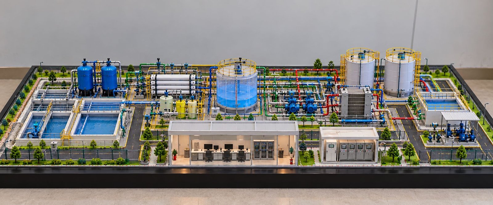
Piping adds important detail to a Waste-to-Energy Plant Model. Moreover, the plant can contain several different pipe routes.
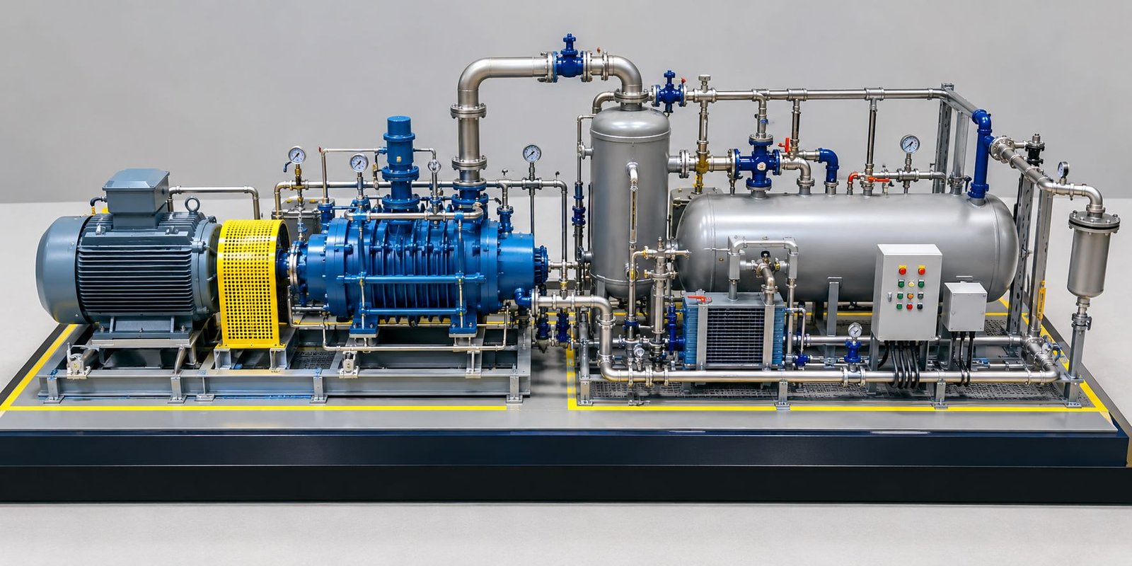
Large pipes can represent steam, exhaust gas and other major connections. Meanwhile, smaller pipes can represent utility and service lines.
Each pipe should follow a logical route between equipment. In addition, pipe supports can hold long horizontal sections.
Small model components can represent elbows, joints, vertical risers and flanges. Furthermore, different pipe sizes can make the model look more realistic.
The designer can use colour coding for process identification when the project requires it. However, the selected colours should match the project’s presentation standard.
Pollution Control Equipment
Modern waste-processing plants can use different systems to control emissions. Therefore, a detailed model can show filter housings, ducts, scrubber units, cyclones and other equipment according to the plant design.
These components can sit between the combustion section and the chimney. Next, large ducts can connect the equipment in a clear sequence.
Platforms and access ladders can surround tall filter units. In addition, small railings can add more industrial detail.
This section adds educational value because it shows that the plant contains systems beyond waste handling and power generation. For example, a cutaway section can expose selected ducts and equipment.
As a result, viewers can understand the connection between the different plant sections more easily.
Chimney and Stack Model
The chimney usually becomes one of the tallest parts of a Waste-to-Energy Plant Model. Therefore, its height creates a strong vertical element and makes the plant easy to identify.
The maker can use a lightweight cylindrical material for the stack. However, the height should always match the selected model scale.
Platforms, ladders and safety railings can surround the upper section. In addition, a small warning light can add detail when the presentation requires it.
The chimney needs a strong connection with the base. As a result, proper support can prevent movement and improve model stability.
Turbine and Power Generation Section
The power-generation section can use a separate turbine hall. This building can contain miniature turbine and generator components.
A cylindrical turbine can connect with large steam pipes. Next, the generator can sit beside the turbine.
A transparent wall can expose the equipment inside the building. Therefore, viewers can see the machinery while the building still keeps its physical form.
Electrical cables can connect the generator area with the transformer and switchgear section. In this way, the model can show the connection between power generation and electrical distribution.
For a working model, LEDs can indicate the power-generation stage. However, the model does not need to copy the complete industrial process. Instead, the visual system can explain the basic concept in a simple and safe way.
Cooling System and Water Section
The cooling section can add another useful feature to Waste-to-Energy Plant Model Making. Depending on the design, the model can show cooling equipment, water tanks, cooling basins and related infrastructure.
A small rectangular water basin can use transparent blue acrylic. In addition, pipes can connect the basin with nearby equipment.
Cylindrical structures can represent storage tanks. Moreover, small ladders and railings can surround the tanks.
This section also adds shape variety to the model. As a result, the plant can include cylindrical tanks, pipes, buildings and other industrial forms instead of only rectangular structures.
Electrical Substation and Transformer Area
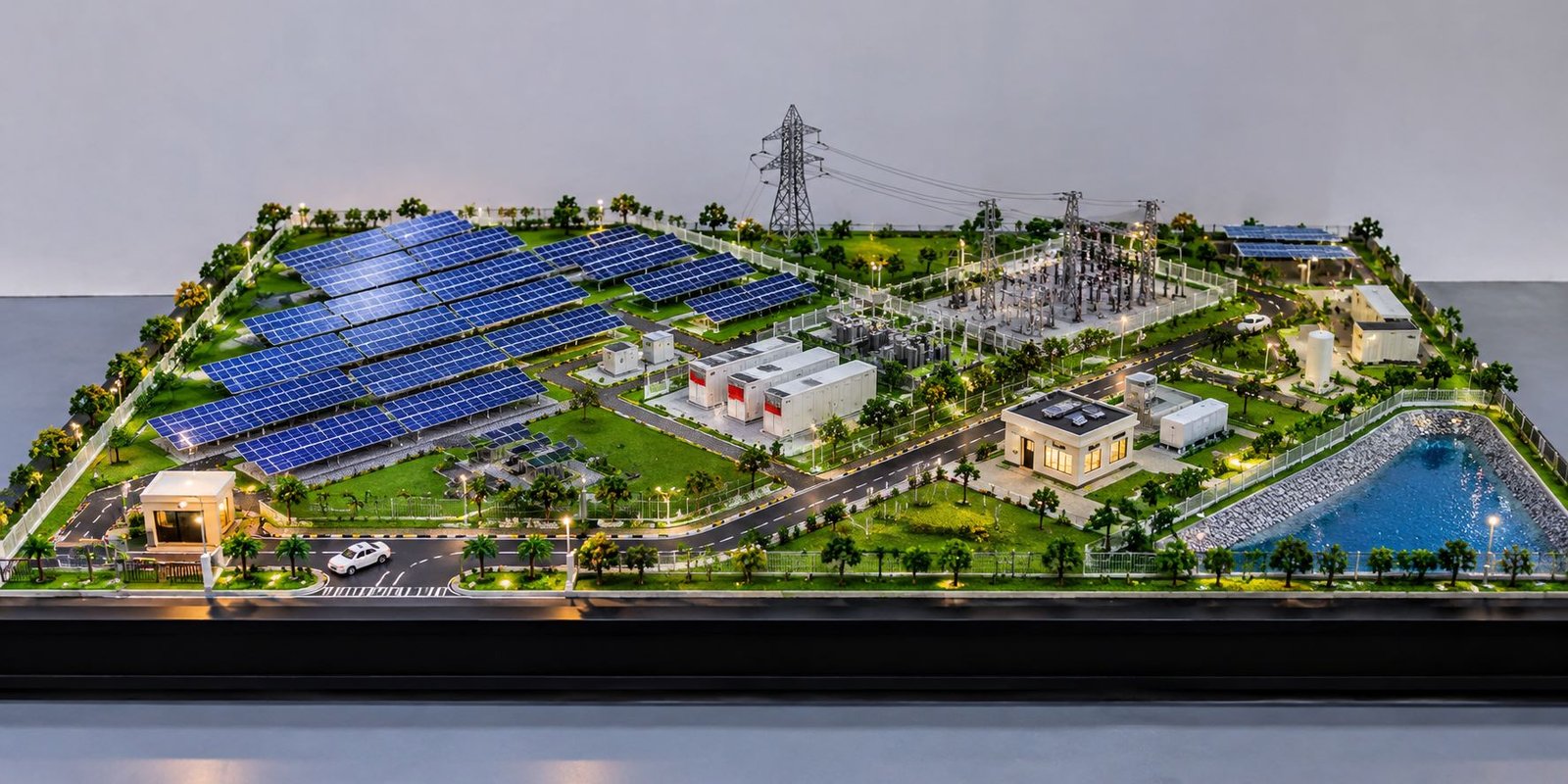
The electrical section can sit on one side of the plant. For example, it can include transformers, switchgear, electrical panels and transmission structures.
Small blocks, coils and insulated parts can represent miniature transformers. Next, electrical cables can connect the transformer area with the power-generation building.
A small transmission tower can stand near the site boundary. In addition, thin wires can connect the tower with the electrical equipment.
Safety fencing should surround the electrical area. Moreover, warning signs and controlled access gates can add more realistic detail.
Control Room and Administration Building
The control room adds an important supporting area to the physical model. Therefore, a small modern building can represent the control and monitoring section.
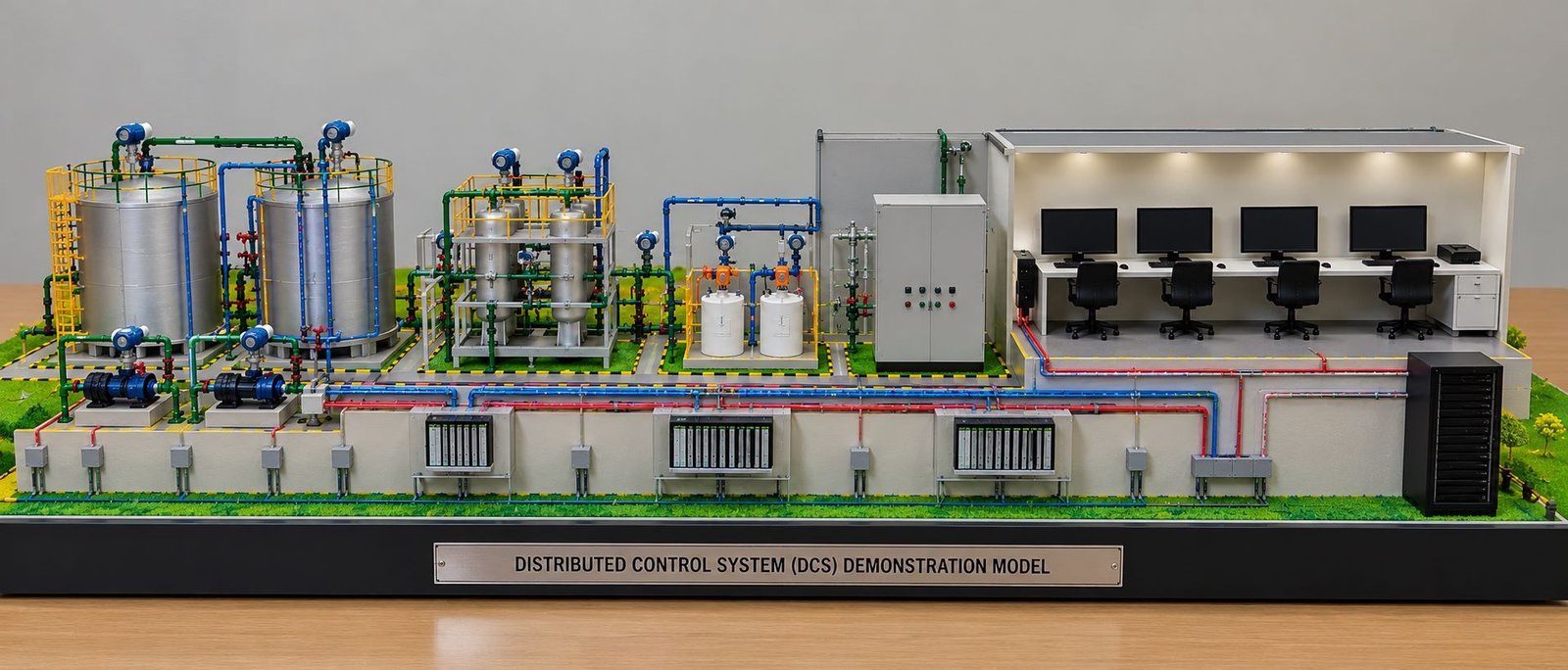
Transparent windows can reveal a miniature control room. For example, small desks, monitors and control panels can add detail when the model scale allows it.
An administration building can sit near the main entrance. In addition, parking spaces, pedestrian paths and landscaping can surround the building.
As a result, these smaller buildings help the model look like a complete industrial facility rather than a simple collection of machines.
Roads, Landscaping and Site Development
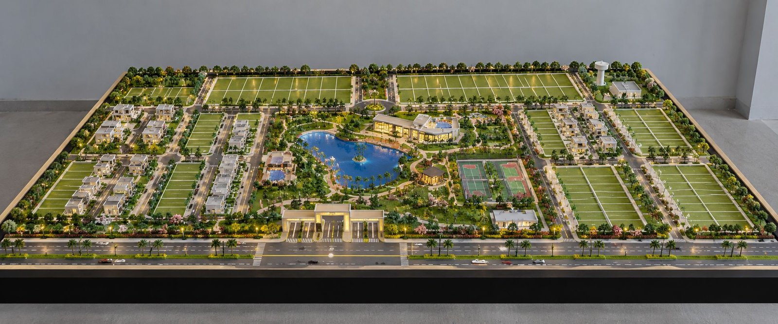
A professional Waste-to-Energy Plant Model should also show the surrounding site infrastructure. Therefore, roads, landscaping and security elements need proper attention.
Dark surface material can represent internal roads. In addition, white lane markings can define the road layout. Small trucks can use these roads to represent waste transportation.
Green areas can surround the buildings. For example, small trees, bushes and grass surfaces can create a complete industrial landscape.
Streetlights can line the main roads. Moreover, security fencing can surround the complete facility.
Finally, the main entrance can include a security gate and barrier. Parking areas can also sit near the administration or control building.
Materials Used for Waste-to-Energy Plant Models
The maker can select different materials according to the model scale and required level of detail.
For example, acrylic works well for transparent walls, windows and display sections. PVC sheets can form buildings and equipment housings. Meanwhile, MDF can provide a strong base and structural support.
3D printing can create detailed machinery, valves, pumps and equipment housings. In addition, it can help create small parts that may be difficult to make by hand.
Metal wires can represent pipes, railings and structural supports. Similarly, aluminium profiles can represent industrial frames.
LEDs can light buildings, roads and selected equipment. Moreover, small motors can add movement when the project requires working components.
Therefore, the material choice should match the model scale, durability needs, budget and presentation purpose.
Scale and Dimensions of Waste-to-Energy Plant Model
Scale selection plays an important role because industrial plants can cover a large area. Therefore, the maker should select the scale before creating the main components.
A smaller scale can show the complete facility. On the other hand, a larger scale can show more equipment detail.
Common model scales include 1:50, 1:100, 1:200 and 1:500. However, the project size and available display space should guide the final choice.
For example, a 10-metre-long object becomes 100 millimetres long at a 1:100 scale.
The same scale should apply to buildings, equipment, vehicles, roads and other major elements. As a result, consistent scaling helps the entire model look realistic.
Working Waste-to-Energy Plant Model
A working model can add another level of presentation. However, the system should remain simple and safe.
For example, a small motor can move a miniature conveyor. In addition, LEDs can represent different process stages. A small fan can show airflow, while another motor can rotate a turbine model.
Switches can control different functions from the baseboard. For instance, one switch can control the plant lighting, while another can operate the conveyor.
A small display can show simple information such as process status or demonstration energy output. As a result, visitors can follow the process more easily.
The goal is not to copy a complete industrial plant at full technical scale. Instead, the working model should give viewers a clear explanation of the major processes.
Physical Appearance and Realistic Detailing
Realistic detailing plays an important role in professional physical model making. Therefore, every major part should have a clean and accurate appearance.
Buildings should have clean edges and correct proportions. Equipment should have suitable supports. Similarly, pipes should connect correctly, while platforms should have proper safety railings.
Small details can improve the overall appearance. For example, doors, windows, ladders, vents, cable trays, valves, tanks and warning signs can make the model look more realistic.
The baseboard should have equal borders around the model. In addition, a black, white or wood-finish border can create a clean presentation.
Lighting should also remain balanced. Too much light can hide small details. Therefore, carefully placed LEDs can highlight important sections without reducing visibility.
Waste-to-Energy Plant Model for Presentation
A detailed physical model can support project presentations for clients, consultants and project teams. Moreover, it can make a complex industrial layout easier to explain.
The model lets viewers understand the relationship between major plant sections without studying several separate drawings.
An open or cutaway design can make the model even more useful. For example, a transparent side can show the machinery inside a building.
Small labels can identify major sections when needed. However, the labels should remain clean and should not cover important physical details.
Waste-to-Energy Plant Model for Exhibition
An exhibition model should attract attention from a distance and provide useful details when visitors come closer.
A large rectangular base with professional lighting can create a strong display. In addition, roads, trees, trucks, equipment and industrial buildings can create a complete miniature environment.
The model should look attractive from the front, sides and slightly elevated angles. Therefore, the designer should arrange the plant so that important sections remain visible from different directions.
A transparent acrylic cover can protect the model from dust. At the same time, it can keep the complete facility visible to visitors.
Educational Use of Waste-to-Energy Models
Educational institutions can use a Waste-to-Energy Plant Model to explain waste management, thermal processing, energy recovery and industrial infrastructure.
Students can understand the connection between waste collection, processing equipment, heat recovery and electricity generation more easily through a three-dimensional model.
Moreover, a working model can make the lesson more interactive. For example, a miniature conveyor can show waste movement, while LEDs can show different process stages.
In addition, the model can support engineering presentations and project demonstrations.
Quality Control in Waste-to-Energy Plant Model Making
The model maker should check quality throughout the entire model-making process. First, the maker should check the base and main building alignment.
The base should remain flat and strong. Buildings should stay properly aligned. In addition, equipment should match the selected scale.
Pipes should have clean joints and should not look loose. Similarly, railings and ladders should remain straight and evenly spaced.
The maker should hide LED wiring wherever possible. However, important components should remain accessible for maintenance.
Finally, the maker should clean the complete model before photography or presentation. Dust, glue marks and uneven edges can reduce the professional appearance.
Conclusion
Waste-to-Energy Plant Model Making creates a detailed physical representation of a complex industrial facility. A well-planned model can show waste receiving, storage, cranes, conveyors, combustion equipment, boilers, pipes, pollution-control systems, turbines, generators, cooling systems, electrical equipment and supporting infrastructure in one complete miniature plant.
Moreover, a professional model should use realistic proportions, clean construction and a logical equipment layout. Transparent sections, cutaway buildings, lighting and selected working parts can make the model easier to understand.
Finally, industrial presentations, engineering projects, exhibitions and educational demonstrations can all use this type of model. Accurate layout, realistic machinery, detailed piping, site development and clean finishing can give the model the appearance of a real industrial facility in miniature.