SCADA Process Control Demonstration Model Making: Detailed Industrial Scale Models
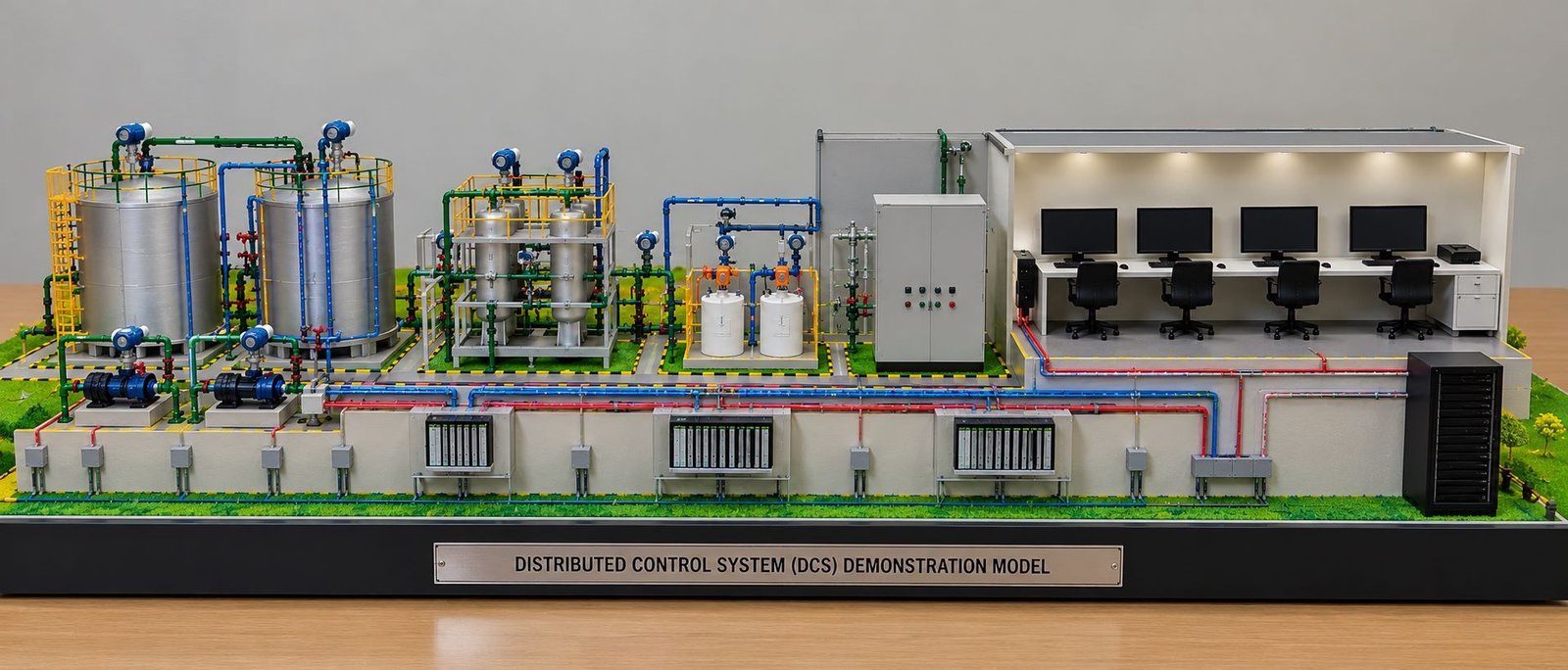
A SCADA Process Control Demonstration Model provides a detailed physical representation of an industrial process control system. It shows how industrial tanks, pumps, pipelines, sensors, valves, control panels, and monitoring equipment work together inside a processing facility. Engineers use these models to explain complex industrial operations during project presentations, technical training sessions, engineering exhibitions, and industrial demonstrations.
SCADA stands for Supervisory Control and Data Acquisition. Industries use SCADA systems to monitor equipment, collect process data, display operating conditions, and supervise industrial operations. A physical demonstration model makes these functions easier to understand because it combines industrial equipment and control infrastructure in one visual presentation.
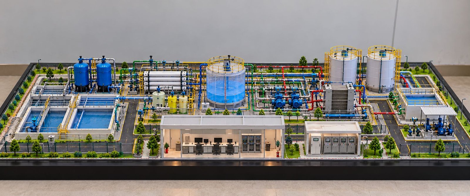
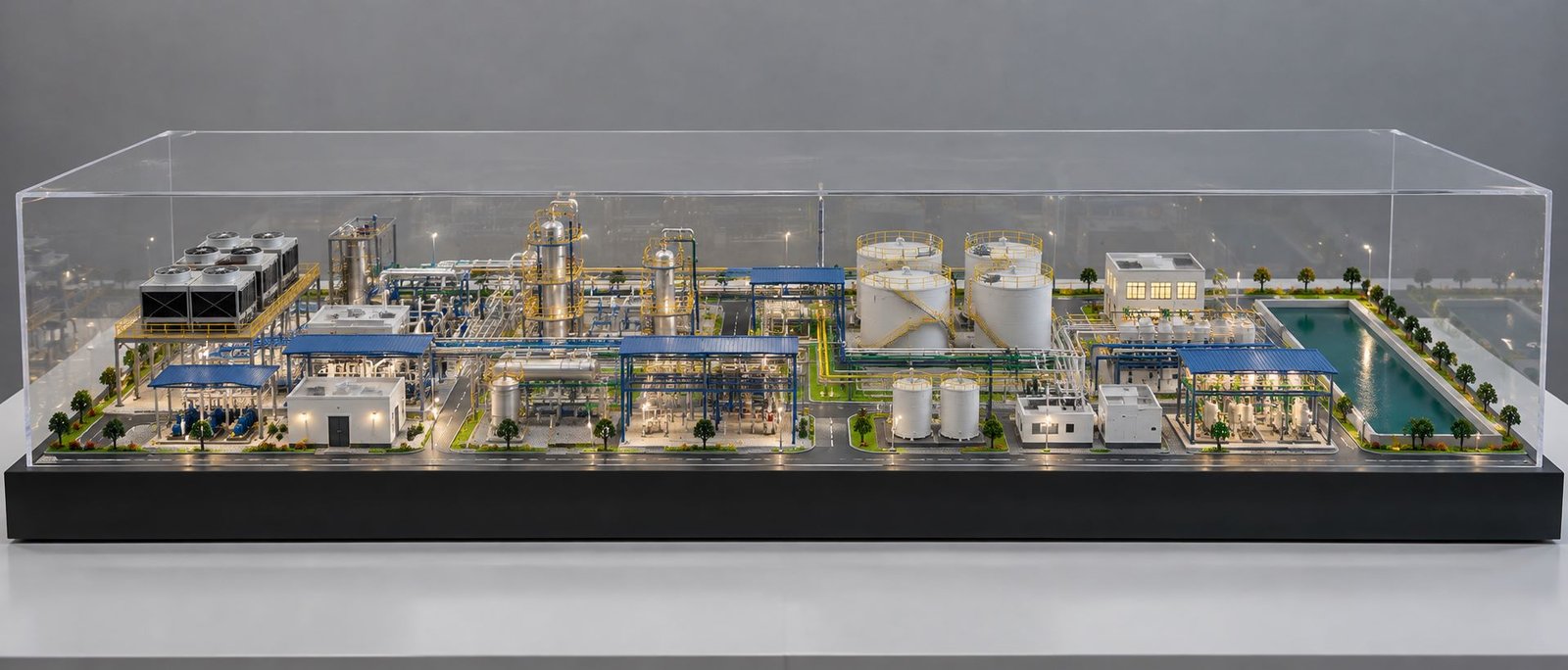
Furthermore, a professionally designed SCADA model can represent a water treatment plant, chemical processing facility, power plant, manufacturing unit, or industrial utility system. Depending on the application, the layout may include storage tanks, filtration equipment, pumping stations, heat exchangers, chemical dosing units, colour-coded pipelines, sensors, and electrical control cabinets.
The model can also feature a compact control room with small computer monitors, PLC and RTU panels, and server cabinets. These components help explain how the supervisory system connects with field equipment. Meanwhile, a wide, low-height layout provides a clear view of the entire industrial installation.
A detailed SCADA Process Control Demonstration Model can support technical communication, equipment visualization, educational demonstrations, and industrial project presentations. Moreover, designers can customize its size, materials, equipment arrangement, and level of functionality according to project requirements.
What Is SCADA Process Control Model Making?
SCADA Process Control Model Making involves creating a physical representation of an industrial facility and its supervisory control system. The model combines miniature process equipment with instrumentation, control hardware, and communication components.
In an actual industrial plant, operators need information about tank levels, flow rates, temperatures, pressures, and equipment status. SCADA systems collect and display this information through a human-machine interface, commonly known as an HMI.
A physical model presents these relationships in a simple and understandable format. For example, viewers can follow a pipeline from a storage tank to a transfer pump, observe its connection to a filtration unit, and identify the instruments that monitor the process.
Additionally, the model can show how sensors communicate with programmable logic controllers, remote terminal units, and supervisory computers.
Industrial Applications of SCADA Process Control Models
SCADA systems support monitoring and supervision in many industrial environments. Therefore, a demonstration model can represent several types of processing facilities.
For example, a water treatment plant model may show filtration, pumping, storage, and distribution. Similarly, a chemical processing model may feature reactors, dosing equipment, heat exchangers, and process pipelines.
Power plants, manufacturing facilities, industrial utility systems, and automated production lines can also benefit from SCADA-based process demonstrations.
Physical Layout of a SCADA Process Control Demonstration Model
The physical layout determines how effectively the model communicates the industrial process. Therefore, designers should arrange each component according to its function and position within the process sequence.
For example, a water treatment model may contain a raw water tank, filtration units, a reverse osmosis system, chemical dosing equipment, treatment tanks, and a final storage section.
The control room can occupy a compact area along the front edge of the baseboard. Behind it, the designer can arrange the main process equipment, pipelines, pumps, and storage vessels.
This arrangement creates a clear view of the entire installation without making the control room unnecessarily large. Furthermore, it provides sufficient space for pipe connections, equipment supports, platforms, and instrumentation.
The final design should reflect the selected industrial application and follow the available engineering drawings wherever possible.
Detailed Components of SCADA Process Control Models
A realistic SCADA demonstration model combines several types of industrial equipment. Each component represents a specific operation within the industrial process.
SCADA Process Control Tanks and Storage Systems
Process tanks store, collect, mix, or treat liquids during industrial operations. They form an essential part of water treatment facilities, chemical processing plants, manufacturing units, and industrial utility systems.
A detailed model may include raw water tanks, intermediate storage tanks, chemical storage vessels, mixing tanks, and final product tanks.
Cylindrical tanks can feature flat or domed tops, support frames, access platforms, ladders, handrails, and inlet and outlet connections. In addition, transparent acrylic can make selected tank interiors visible and improve the presentation of internal details.
The designer can also add miniature level indicators to demonstrate how the control system monitors the quantity of liquid inside each tank.
The position of each tank should follow the intended process sequence. As a result, viewers can understand where materials enter the plant, how the process changes them, and where the materials move next.
SCADA Process Control Pumps and Pumping Stations
Pumps move liquids between tanks and process equipment. They also maintain the flow required for filtration, circulation, cooling, and distribution.
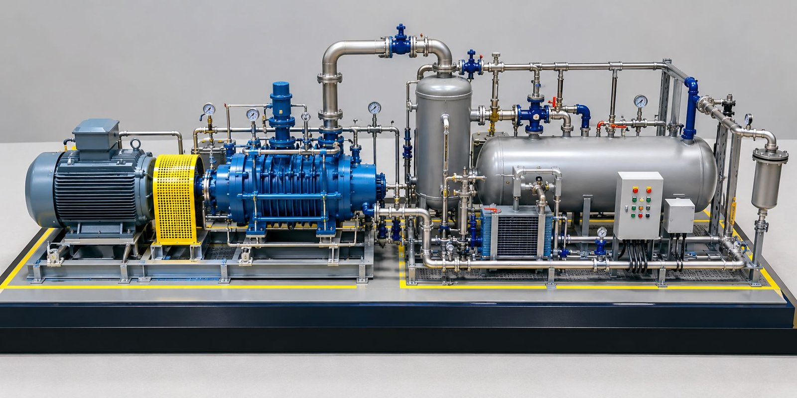
The model may include centrifugal pumps, transfer pumps, pressure pumps, circulation pumps, and chemical dosing pumps. Each miniature pump can feature a motor housing, pump casing, mounting base, and inlet and outlet connections.
Furthermore, small flanges, valves, connecting pipes, and motor details help create a realistic industrial appearance.
The designer can also represent duty and standby pump arrangements where the industrial application requires continuous operation. This feature helps explain how facilities maintain process availability when one pump requires maintenance.
SCADA systems can monitor pump status, motor faults, operating conditions, and relevant process measurements. For example, a functional demonstration model can use small indicator lights to represent running, stopped, or fault conditions.
SCADA Process Control Piping Network
The piping network connects tanks, pumps, filters, valves, and other process equipment. It also helps viewers understand the movement of fluids throughout the installation.
Small-diameter tubes, plastic pipes, miniature fittings, and fabricated connectors can reproduce the appearance of industrial pipework.
Different colours can distinguish process lines. For example, blue pipes may represent water, while other colours can identify chemical dosing lines, cooling water, or selected utility services. The colour scheme should remain consistent throughout the model.
Moreover, the piping network can include elbows, tees, reducers, flanges, isolation valves, control valves, and manifolds. Pipe supports and brackets add further technical detail.
The designer should route the pipes neatly and avoid unnecessary crossings. Consequently, viewers can follow the process connections without losing sight of the main equipment.
When engineering drawings are available, the piping layout can follow the relevant process documentation or piping and instrumentation diagram (P&ID). This approach helps maintain consistency between the physical model and the intended industrial arrangement.
SCADA Process Control Filtration and RO Systems
Filtration equipment plays an important role in water treatment and many industrial processes. A detailed model can represent the equipment used to remove suspended particles, separate impurities, or prepare water for further treatment.
A filtration section may contain pressure vessels, cartridge filters, membrane housings, connecting pipelines, valves, and pressure monitoring instruments.
A reverse osmosis (RO) system can feature several horizontal membrane housings mounted on a miniature structural frame. The assembly may also include feed connections, concentrate outlets, treated water pipelines, and associated pumps.
Additionally, pressure indicators and flow meters can illustrate how the control system monitors operating conditions across the filtration section.
The equipment should maintain consistent proportions with the surrounding tanks and pipelines. This creates a more convincing industrial presentation and makes the overall process easier to understand.
SCADA Process Control Chemical Dosing System
Chemical dosing systems introduce controlled quantities of chemicals into an industrial process. Water treatment plants and chemical processing facilities commonly use these systems.
A miniature dosing unit can include chemical storage containers, dosing pumps, injection points, small-diameter pipes, valves, and instrument connections.
The designer should position the dosing equipment near the relevant treatment tank or process pipeline. Therefore, viewers can identify where the chemicals enter the system.
In addition, labels can identify the dosing pumps and explain their role in the treatment process.
For exhibitions and training displays, the model can demonstrate dosing operations through simulated signals rather than actual industrial chemicals. This approach keeps the demonstration practical and suitable for indoor display.
SCADA Process Control Heat Exchangers and Equipment
Heat exchangers transfer heat between fluids. Industries use them in chemical processing, power generation, manufacturing, and industrial utility systems.
A miniature shell-and-tube heat exchanger can feature a cylindrical body, support frame, inlet connections, outlet connections, and associated piping.
Depending on the application, the model may also include reactors, mixers, separators, compressors, filters, and pressure vessels.
Furthermore, the designer should position each component according to its role in the process. This arrangement helps viewers understand how the equipment interacts with other sections of the plant.
SCADA Process Control Room and Monitoring Equipment
The control room represents the area where operators supervise industrial operations. It connects the physical process with the monitoring and control infrastructure.
A detailed model can feature a compact building with transparent front panels, miniature desks, small computer monitors, operator chairs, and electrical equipment cabinets.
The control room should remain proportionate to the rest of the installation. Smaller workstations help preserve the wide, low-height appearance of the model while leaving sufficient space for the main process equipment.
SCADA Process Control Computer Workstations
Computer workstations provide a visual connection between the industrial process and its monitoring system.
The control room can include small desktop monitors mounted on miniature desks. Their screens can remain switched off when the model focuses on the physical equipment and industrial layout.
Alternatively, a functional demonstration model can use screens to display simulated process diagrams, equipment status, and HMI information.
The monitors should match the scale of the desks, chairs, and control room structure. Otherwise, oversized computers can distract viewers from the main industrial installation.
PLC and RTU Panels in SCADA Process Control
A Programmable Logic Controller (PLC) receives input signals and executes programmed control logic. A Remote Terminal Unit (RTU) collects field information and communicates with supervisory systems, depending on the industrial architecture.
A detailed model can represent these devices through compact electrical cabinets. The cabinets may feature doors, ventilation openings, cable entries, indicator lights, and identification labels.
The designer can position the control panels near the control room or within a dedicated electrical equipment section.
Moreover, the physical arrangement can illustrate how field instruments connect to control hardware and how the system communicates with the supervisory interface.
SCADA Process Control Server Cabinets
Server cabinets represent the computing and communication infrastructure associated with a SCADA installation.
A miniature server rack may include equipment panels, ventilation details, status indicators, and a compact enclosure. The model can also feature network cabinets and communication panels when the project requires them.
These components demonstrate that industrial supervisory control depends on suitable hardware, communication systems, software, and configuration rather than a computer screen alone.
Sensors and Instrumentation in SCADA Process Control
Instrumentation provides information about the physical process. Sensors and transmitters measure operating conditions, while control devices respond to appropriate signals.
Level Sensors for SCADA Process Monitoring
Level sensors measure or detect the amount of material inside a tank. They help operators monitor storage and treatment processes.
A miniature sensor can appear near the tank wall, with an identified connection to the control system. Additionally, the model can show how tank-level information helps operators supervise filling and emptying operations.
Flow Meters and Pressure Transmitters
Flow meters measure the rate at which a fluid moves through a pipeline. Pressure transmitters measure pressure inside pipelines, tanks, and process equipment.
The model can include miniature flow meters along the main process lines and small pressure instrument housings near pumps or filtration equipment.
Consequently, viewers can understand how flow and pressure measurements support process monitoring and equipment supervision.
Temperature Sensors and Control Valves
Temperature sensors monitor process temperature. Designers can position them near heat exchangers, reactors, boilers, or other temperature-sensitive equipment.
Control valves regulate flow according to process requirements. Actuators operate these valves in response to control signals or other operating mechanisms.
Moreover, labels can distinguish automatic control valves from manually operated isolation valves. This distinction helps explain how the control system influences selected process operations.
How SCADA Process Control Systems Work
A SCADA system collects information from field equipment, communicates with control devices, and presents operating data to authorized users.
A physical demonstration model can explain this operation through the relationship between industrial equipment, instrumentation, control panels, and supervisory monitoring.
Field Data Collection in SCADA Systems
First, sensors measure process conditions such as pressure, temperature, flow, and tank level.
For example, a level transmitter can report the liquid level inside a storage tank. Similarly, a flow meter can measure the movement of water through a treatment pipeline.
These signals provide information about the condition of the process. Therefore, field data helps the control system monitor industrial operations.
PLC and RTU Communication in Process Control
Next, the PLC or RTU receives relevant signals and processes or communicates them according to the configured system.
The PLC may execute local control logic, while an RTU may collect information from remote equipment. However, their exact roles depend on the industrial architecture.
Additionally, suitable communication links transfer the required information to the supervisory system.
SCADA Process Monitoring and Supervisory Control
The SCADA software displays process information through a human-machine interface (HMI).
Operators may view equipment status, process measurements, alarms, and historical trends. Depending on the system, they may also issue authorized commands.
Meanwhile, the physical model can represent this arrangement by positioning the control room, PLC cabinets, and server equipment near the main industrial installation.
Control Actions and Feedback in SCADA Systems
Finally, the control system may send an authorized command to a pump, valve, or another device. The equipment responds according to the configured logic and operating conditions.
Feedback signals then provide information about equipment status or the resulting process condition.
A functional demonstration model can illustrate selected operations using suitable low-voltage components, miniature indicators, simulated sensors, or a small controller. However, a static model explains these relationships visually without providing live SCADA functionality.
SCADA Process Control Model Design and Fabrication
A successful physical model combines accurate proportions, realistic equipment details, an organized layout, and suitable materials. Therefore, the designer should plan the fabrication process around the project’s technical and presentation requirements.
Wide and Low-Height SCADA Model Design
A wide, low-height design helps present the complete industrial installation in a single view. It also provides enough horizontal space for several process sections.
A rectangular baseboard supports the tanks, pumps, piping, control room, and electrical equipment. The base can feature a clean black, grey, or neutral finish.
Additionally, a consistent border creates a neat presentation and separates the model from its surroundings.
The designer should divide the installation into clear process sections. For example, a water treatment model may place raw water storage and filtration equipment on one side, treatment tanks in the middle, and final storage equipment on the other side.
The control room can occupy a compact section along the front edge, with PLC and server cabinets nearby. Consequently, the layout provides a clear view of the main equipment while maintaining a balanced composition.
Materials for SCADA Process Control Model Making
The materials and fabrication techniques determine the appearance, durability, and detailing of the finished model.
Acrylic can represent transparent tanks, control room windows, protective covers, and selected equipment housings. It helps viewers see internal details where transparency improves the technical presentation.
Small plastic tubes and connectors can reproduce the appearance of industrial pipework. Different colours can identify separate process lines. In addition, consistent diameters, clean joints, and neatly aligned routes improve the overall finish.
Board materials, plastic sheets, miniature metal sections, and fabricated supports can form the baseboard, buildings, platforms, equipment frames, and cabinets.
Yellow safety railings, access ladders, walkways, and platform edges add further industrial detail. Meanwhile, a suitable surface finish helps unify the complete installation.
3D Printing and Laser Cutting for Industrial Models
3D printing can produce complex equipment housings, pump casings, instrument supports, and customized miniature components.
Laser cutting can create accurate panels, structural elements, platforms, and selected building components.
Furthermore, careful assembly, painting, surface finishing, and miniature fittings help create a realistic physical model. The designer should also check component proportions and pipe routing before completing the final assembly.
Applications of SCADA Process Control Demonstration Models
SCADA Process Control Models for Industrial Presentations
Engineering teams can use physical models to explain equipment arrangements, process flow, and control infrastructure during project meetings.
The model provides a visual reference that complements engineering drawings and technical documentation. As a result, stakeholders can understand the overall installation more easily.
SCADA Models for Engineering Training Centres
Training centres can use SCADA demonstration models to introduce learners to industrial instrumentation, automation, process monitoring, and control hardware.
The physical arrangement helps connect theoretical concepts with recognizable industrial equipment. Additionally, interactive features can demonstrate selected operating principles.
SCADA Demonstration Models for Industrial Exhibitions
A detailed model can serve as a display at industrial exhibitions, trade shows, and engineering conferences.
Its wide layout helps visitors view several process sections without losing sight of the overall installation. Moreover, realistic detailing can make the display more informative and engaging.
SCADA Process Control Models for Engineering Colleges
Educational institutions can use these models to demonstrate industrial automation, PLC systems, instrumentation, and supervisory monitoring.
Depending on the learning objectives, the model can remain static or include selected functional components. Therefore, designers can adapt the model to different teaching and demonstration requirements.
Benefits of SCADA Process Control Demonstration Models
Clear process visualization: The model presents tanks, pumps, piping, instruments, and control equipment together in one physical installation.
Improved technical communication: Engineers can explain equipment relationships and process sequences during presentations.
Realistic industrial appearance: Detailed pipes, valves, platforms, cabinets, and miniature structures create a convincing representation of an industrial facility.
Project-specific design: The model can follow engineering drawings, reference photographs, and supplied equipment layouts.
Training support: Learners can understand the relationship between field devices, control hardware, and supervisory monitoring.
Flexible presentation: A wide baseboard and low-height arrangement provide a clear view of the complete model.
Optional functionality: Suitable sensors, low-voltage indicators, miniature motors, and demonstration controllers can illustrate selected operating principles.
Furthermore, the model can combine several process sections into one organized installation, making it easier to present complex engineering information in a limited display area.
How to Plan a SCADA Process Control Model
Define the Industrial Application
First, identify the process that the model must represent. It could involve water treatment, chemical processing, power generation, manufacturing, or another industrial application.
This decision determines the required equipment and the overall layout.
Prepare the Equipment Layout
Next, arrange the main equipment according to the intended process sequence. Provide sufficient space for pipe connections, instruments, supports, and access areas.
A wide layout may be suitable when the model must fit a feature image or presentation display.
Review Engineering Drawings
P&IDs, CAD drawings, equipment layouts, and reference photographs help guide the design.
These documents provide useful information about equipment placement, process connections, and the intended relationship between components. Consequently, the design can reflect the actual project more accurately.
Select Materials and Fabrication Methods
Choose suitable materials for tanks, pipes, platforms, cabinets, and buildings.
The fabrication approach should meet the required level of detail, strength, and finish. Moreover, designers should consider the intended display environment when selecting materials.
Decide on Static or Functional Features
A static model focuses on physical appearance, equipment layout, and visual explanation.
In contrast, a functional model may include low-voltage indicators, simulated process signals, miniature motors, or selected control components.
Define the required functions before fabrication because they influence wiring, component selection, assembly, and testing.
Inspect the Finished Model
Finally, check the equipment placement, piping connections, labels, surface finish, baseboard, and overall proportions.
For a functional model, test the selected demonstration features before delivery. This final inspection helps maintain a consistent presentation quality.
Frequently Asked Questions About SCADA Process Control Models
What Is a SCADA Process Control Demonstration Model?
It is a physical scale model that represents an industrial process and shows how equipment, sensors, control panels, and supervisory monitoring systems work together.
Which Components Can the Model Include?
The model can include industrial tanks, pumps, filters, RO membrane skids, chemical dosing systems, heat exchangers, piping networks, flow meters, pressure transmitters, level sensors, PLC and RTU cabinets, server racks, and a compact control room.
Can the Model Have a Wide Layout and Low Height?
Yes. Designers can arrange the equipment across a wide rectangular baseboard while keeping the overall height relatively low. This approach works well for presentations, exhibitions, and website feature images.
Can the Computer Screens Remain Switched Off?
Yes. The model can include small computer monitors with their screens switched off. This keeps the focus on the physical industrial equipment and maintains a clean control room appearance.
Can the Model Demonstrate Actual SCADA Functions?
A functional model can demonstrate selected operations using suitable sensors, low-voltage components, simulated process signals, and control hardware. However, a static physical model does not automatically provide live SCADA functionality.
Which Materials Are Suitable for Fabrication?
Acrylic, plastic sheets, miniature tubes, board materials, metal sections, and 3D-printed components can support different parts of the model. The final selection depends on the required detailing and design.
Can Engineering Drawings Guide the Model Design?
Yes. CAD drawings, P&IDs, equipment layouts, and reference photographs can guide the fabrication process. The available technical information determines the achievable level of accuracy.
Who Can Use a SCADA Demonstration Model?
Industrial companies, EPC contractors, engineering consultants, training centres, educational institutions, and project teams can use these models for technical presentations, training, and exhibitions.
Conclusion
A SCADA Process Control Demonstration Model provides a practical way to explain the relationship between industrial equipment, field instrumentation, control hardware, and supervisory monitoring.
From process tanks and pumping stations to filtration units, colour-coded pipelines, compact control rooms, PLC and RTU panels, and miniature instruments, every component contributes to the technical presentation.
Careful attention to proportions, pipe routing, labels, materials, and baseboard design helps create a clear and realistic physical model. Furthermore, a wide, low-height layout allows viewers to understand the complete industrial installation at a glance.
Whether the objective involves technical training, industrial exhibitions, project presentations, or engineering education, a detailed SCADA demonstration model can make complex process control arrangements easier to visualize and explain.