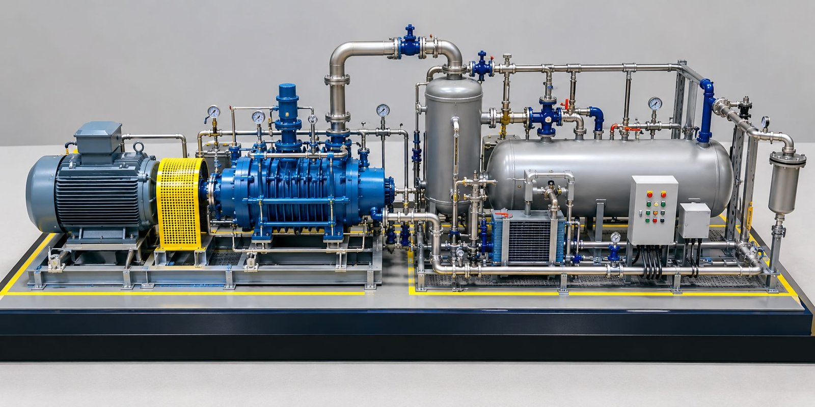
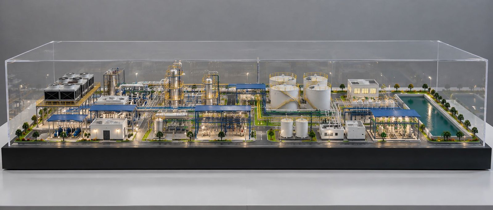
Solar Energy Ecosystem Model Making: Detailed Renewable Energy Scale Models
A solar energy ecosystem brings together solar panels, electrical equipment, battery storage, power transmission systems, and supporting infrastructure. Each component plays an important role in generating, managing, and delivering electricity. A detailed Solar Energy Ecosystem Model shows how these components work together within a real renewable energy project.
Today, solar energy projects play an important role in modern infrastructure. Solar power companies, engineering consultants, EPC contractors, research institutions, and educational organisations need clear ways to present their projects. For this reason, many organisations use physical scale models to explain complex layouts through realistic three-dimensional displays.
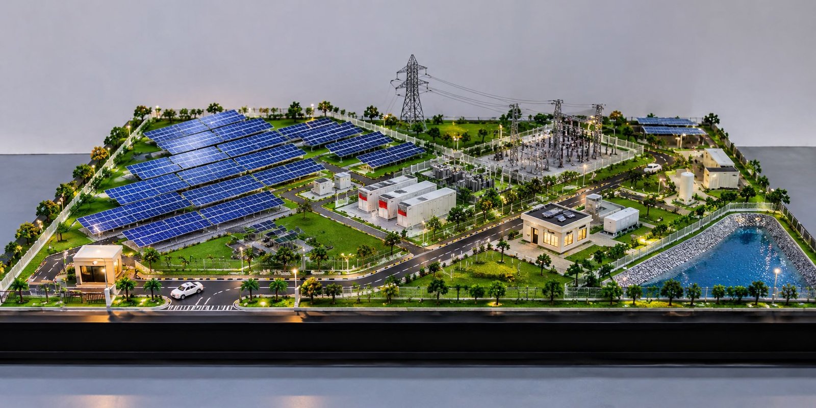
Solar Energy Ecosystem Model Making combines engineering details, miniature structures, site planning, and professional presentation. Instead of showing only a few solar panels, a complete model represents the entire facility, including panel arrays, inverter stations, transformers, battery storage units, substations, transmission towers, control buildings, internal roads, and landscaped areas.
These models support project presentations, technical exhibitions, educational demonstrations, planning meetings, and client discussions. In addition, a carefully designed Solar Power Plant Scale Model helps viewers understand equipment placement, land use, access routes, and the movement of electricity through different stages of the system.
What Is a Solar Energy Ecosystem Model?
A Solar Energy Ecosystem Model is a physical miniature of a renewable energy facility. It represents the main equipment, buildings, electrical connections, and site features that make up a solar power project.
A basic solar panel model usually focuses on the panels and their working principle. In contrast, a complete solar energy ecosystem model presents the wider system, from electricity generation to storage and grid connection.
The model may include photovoltaic panels, mounting structures, inverter cabinets, transformers, battery containers, electrical substations, transmission towers, maintenance buildings, security fencing, roads, and drainage areas. However, the exact components depend on the project requirements.
For example, a large solar farm may need extensive panel fields and high-voltage infrastructure. Meanwhile, a smaller demonstration facility may focus on solar generation, battery storage, and a simple electrical connection.
How the Solar Energy System Works
Solar panels capture sunlight and convert it into direct current electricity. Next, inverters convert this electricity into alternating current for use by suitable electrical systems or transfer through the grid connection.
Transformers adjust voltage levels according to the system design. After that, substations and associated switchgear manage electrical connections, while battery energy storage systems can store electricity for later use.
A physical model can represent each stage through the position and appearance of the equipment. For instance, panel arrays occupy the generation area, inverter stations sit near the panel fields, and the substation connects the facility with the wider power network.
As a result, viewers can understand how individual components contribute to the complete energy system.
Why Choose a Complete Energy Ecosystem Model?
A complete model provides more information than a simple display of solar panels. It shows the relationship between equipment, buildings, roads, storage areas, and power transmission infrastructure.
Project developers can use it to explain proposed layouts, while engineering teams can discuss equipment placement and access requirements. Similarly, educational institutions can use the model to introduce renewable energy concepts through a physical display.
Therefore, a Solar Energy Ecosystem Model offers a practical way to present complex energy infrastructure in one organised view.
Main Components of a Solar Power Plant Scale Model
A realistic Solar Power Plant Scale Model requires careful planning and accurate miniature details. Each component should have the right proportions and a logical position within the overall site.
Solar Panel Arrays
Solar panels form the main visual feature of most solar farm models. Model makers arrange them in repeated rows to represent a large photovoltaic installation.
Deep blue or dark navy panel surfaces, fine cell divisions, slim frames, and realistic mounting structures improve the appearance of each array. Furthermore, consistent row spacing helps the model resemble a professionally planned solar facility.
Ground-mounted panels work particularly well in utility-scale solar models. Small support legs, gravel paths, maintenance corridors, and cable routes add further detail.
Some projects may also include rooftop solar panels on control buildings, warehouses, industrial structures, or other facilities. This arrangement demonstrates how different solar installations can contribute to a wider renewable energy network.
Inverter Stations and Electrical Equipment
Inverters convert the direct current generated by solar panels into alternating current. A detailed engineering model can show these units as miniature cabinets or small equipment stations placed near the panel arrays.
Transformers, electrical cabinets, switchgear enclosures, and cable routes help complete this section. At the same time, their arrangement should follow the project layout wherever drawings are available.
White, light grey, and metallic finishes can distinguish electrical equipment from the darker solar panels. Small doors, ventilation grilles, raised platforms, and access paths add realism without making the layout unnecessarily crowded.
Battery Energy Storage System
Battery energy storage plays an important role in many modern renewable energy projects. These systems store electricity for later use and can help manage differences between energy generation and demand.
A physical Solar Energy Ecosystem Model can represent battery storage through rows of miniature industrial containers. The area may include ventilation details, electrical cabinets, access paths, and clearly defined safety clearances.
Additionally, model makers should position the storage units logically in relation to the inverter stations and substation. This arrangement helps viewers understand how the different systems connect.
Electrical Substation and Switchyard
The electrical substation is often one of the most detailed sections of an engineering scale model. It represents the equipment that connects the solar facility with the power transmission network.
A miniature switchyard may feature transformers, circuit breakers, busbars, isolators, support frames, and control equipment. Fine metal or plastic components can reproduce the appearance of these structures.
The model should maintain clear spacing between the main equipment units. Moreover, internal access routes and a defined boundary can make the substation look more realistic.
Transmission Towers and Power Lines
Transmission towers show how electricity moves from the solar facility towards the wider grid. Their lattice frames, cross-arms, insulators, and connecting conductors create an important visual feature.
However, tower height must match the scale of the rest of the model. Oversized towers can hide the panel arrays and disturb the overall composition.
For a balanced design, the model maker can position the towers towards the rear or along one side of the baseboard. Consequently, the main solar installation remains visible while the model still represents the power transmission system.
Control Buildings and Maintenance Facilities
Control buildings represent the operational side of a solar power plant. These structures may contain monitoring rooms, offices, maintenance areas, security facilities, and electrical control spaces.
Miniature buildings can feature realistic doors, windows, roof details, external lights, and service entrances. In addition, a security cabin, parking area, and small maintenance vehicles can add further detail.
Together, these elements transform a collection of solar panels into a complete industrial facility.
Renewable Energy Engineering Model Making for Integrated Projects
Renewable energy developments can combine several technologies within one project. A detailed Renewable Energy Engineering Model can bring these systems together in a single physical presentation.
Solar and Wind Energy Integration
Some renewable energy projects combine solar panels with wind turbines. A hybrid energy model can represent both technologies while showing their supporting infrastructure.
Solar panel arrays may occupy the largest section of the site, while wind turbines stand in a separate zone. Meanwhile, access roads, equipment areas, and electrical connections help explain the relationship between the two systems.
The layout should maintain realistic spacing and suitable proportions. This approach gives each technology enough visual space for viewers to understand its role.
Smart Grid and Power Distribution
A smart energy ecosystem may include substations, distribution equipment, monitoring buildings, control centres, and grid connection facilities.
The model can show how the solar installation connects to the wider electrical network. Carefully planned cable routes and clearly separated equipment zones make the layout easier to understand.
For technical or educational presentations, a small legend can explain the main components. However, the displayed connections should reflect the supplied project information rather than suggest that every solar plant uses the same design.
Electric Vehicle Charging Stations
Electric vehicle charging infrastructure can add another dimension to a renewable energy model. This feature works especially well for smart cities, industrial campuses, commercial developments, and integrated energy projects.
A miniature charging area may include charging posts, parking bays, small vehicles, pedestrian paths, and solar canopies. In this way, the model can show how solar power may support electric mobility when the necessary electrical infrastructure is available.
Sustainable Buildings and Green Spaces
Green buildings, landscaped areas, drainage channels, and water collection features help present the wider environmental planning of a renewable energy facility.
Miniature trees, grass surfaces, gravel paths, and small water bodies can improve the visual quality of the display. Nevertheless, landscaping should not cover essential equipment or make the engineering layout difficult to understand.
The best design balances technical information with an attractive physical presentation.
Solar Farm Model Making and Site Layout Planning
A successful Solar Farm Model Making project starts with an accurate site layout. Before fabrication begins, the design team should review the available drawings, equipment dimensions, boundary measurements, and project requirements.
Land Use and Panel Arrangement
The panel fields should follow the intended site plan. Regular rows, consistent gaps, and clear maintenance corridors create a convincing representation of a large solar installation.
The design team should consider the site boundary, panel orientation, access needs, and position of major equipment. Whenever engineering drawings are available, the model should preserve important dimensions and spatial relationships as closely as the chosen scale allows.
Internal Roads and Maintenance Access
Internal roads connect panel fields with inverter stations, battery storage compounds, substations, and control buildings. A realistic model should present these routes as one connected network.
Road markings, junctions, turning areas, gates, and small service vehicles can improve the level of detail. In addition, consistent road widths help the layout look organised.
The road network should provide logical access throughout the site without separating important components unnecessarily.
Drainage and Water Management
Drainage features help explain how a solar facility manages rainwater and ground conditions. Depending on the project, the model may include channels, culverts, collection ponds, embankments, and water management areas.
A miniature reservoir can add visual interest while representing an actual project feature. Its shape and location should follow the intended site design.
Security Fencing and Site Boundaries
Boundary fencing, access gates, security cabins, and perimeter roads define the operating area of a solar facility.
Fine mesh fencing and proportionate gate structures create a convincing industrial appearance. The fence should follow the site boundary and maintain a consistent distance from the main equipment.
These small details make the model feel complete and help viewers understand the organisation of the facility.
Materials and Fabrication Techniques for Solar Energy Models
The right materials improve the accuracy, durability, and appearance of a solar energy model. Model makers often combine several fabrication methods to create different components.
Acrylic, PVC, MDF, and Foam
Acrylic sheets work well for transparent covers, display elements, and selected building details. PVC sheets can form equipment cabinets and miniature structures, while MDF provides a stable baseboard for many physical models.
Foam boards and modelling materials help create terrain, raised platforms, landscaped areas, and lightweight site features.
The team should select materials according to the required dimensions, level of detail, finish, and expected use of the final model.
3D Printing for Detailed Components
3D printing helps produce complex miniature parts that require accurate shapes and consistent dimensions. These parts may include transformer housings, inverter cabinets, custom brackets, mounting structures, turbine components, and other technical details.
Printed components often need surface preparation, sanding, painting, and careful assembly before they reach the desired finish.
Furthermore, combining 3D printing with laser cutting and manual fabrication allows the model maker to create both complex equipment and larger site structures.
Laser Cutting for Accurate Parts
Laser cutting supports precise fabrication of baseboard sections, building walls, equipment platforms, panel supports, and selected fencing elements.
Repeated parts can maintain consistent dimensions, which improves the appearance of the completed model. However, careful assembly and finishing remain essential for a professional result.
Painting and Surface Finishing
Colour selection should distinguish different parts of the facility. Solar panels may feature deep blue surfaces, electrical cabinets can use white or light grey, and roads can have charcoal grey finishes.
Metallic details, gravel textures, green landscaping, and small road markings provide visual depth. As a result, even a wide model can show a high level of detail without looking overcrowded.
Choosing the Right Scale and Baseboard Dimensions
The proportions of a solar energy model affect both its technical presentation and its appearance in photographs. A wide, low-height design often works well for a website feature image because it shows more of the site in one frame.
Selecting a Suitable Model Scale
The model scale depends on the site size, available space, viewing distance, and level of detail.
A smaller scale can represent a large solar farm within a compact baseboard. In contrast, a larger scale allows viewers to inspect individual equipment units and structural details more easily.
Every major component should follow a consistent scale relationship. Disproportionate panels, oversized buildings, or excessively tall transmission towers can reduce the realism of the complete model.
Designing a Wide Rectangular Baseboard
A rectangular baseboard gives the model a clean and organised foundation. Its length and width should reflect the project layout and the number of components that need to fit within the display.
For a wide composition, the solar arrays can occupy one side, while the substation, inverter stations, battery containers, and control buildings fill the remaining space.
The front edge should remain clean, and the border should look consistent on all sides. Additionally, a dark or neutral baseboard creates a clear separation between the miniature landscape and the studio background.
Lighting and Photography
Small LED lights can highlight control buildings, internal roads, entrance gates, and selected outdoor facilities. Subtle lighting helps viewers notice important details without overpowering the natural colours.
Soft studio lighting reveals the miniature structures while reducing harsh reflections on acrylic surfaces. A slightly elevated front view provides a useful balance between the overall layout and the three-dimensional appearance of individual components.
For a feature image, a wide landscape composition should keep the entire baseboard visible and leave enough space around the model for a clean presentation.
Applications of Solar Energy Ecosystem Scale Models
Solar energy scale models serve different purposes across the renewable energy industry, education, infrastructure planning, and technical exhibitions.
Solar Project Developers and EPC Contractors
Project developers and engineering, procurement, and construction contractors can use physical models to present proposed facilities and explain their main infrastructure.
A detailed display helps clients understand the position of panel fields, equipment stations, battery storage, access roads, and grid connections. Moreover, it provides a shared reference during project discussions.
Renewable Energy Companies and Investors
Renewable energy companies can present custom scale models during investor meetings, project proposals, corporate presentations, and industry events.
A project-specific model communicates the physical layout more clearly than a generic miniature installation. It can also help stakeholders understand the project’s planned infrastructure at a glance.
Engineering Colleges and Research Centres
Educational institutions can use Solar Power Plant Models to explain photovoltaic generation, electrical conversion, battery storage, and transmission systems.
A static display provides an overview of the facility, while a working demonstration can include selected electrical circuits, indicator lights, or functional solar components.
The level of functionality should match the learning objectives and the available budget.
Government and Infrastructure Presentations
Infrastructure teams may require scale models to explain renewable energy developments, land use, utility connections, and supporting facilities.
A physical model makes spatial information easier to understand for audiences who do not work directly with technical drawings. Therefore, it can support discussions between project teams and other stakeholders.
Trade Shows and Renewable Energy Exhibitions
Exhibition models need a clean finish and a clear visual layout. Visitors may view the display from different directions, so the major components should remain easy to identify from the intended viewing angles.
A wide baseboard, detailed solar arrays, realistic equipment, and well-planned landscaping can create a strong professional presentation.
Custom Solar Energy Model Making for Different Projects
Every renewable energy project has different site conditions, equipment requirements, and presentation goals. Custom Solar Energy Model Making allows the display to reflect the actual project instead of relying on a standard layout.
Static Solar Energy Ecosystem Models
Static models focus on appearance, proportions, and site planning. They suit boardrooms, offices, exhibitions, project presentations, and engineering displays.
A static model can include solar arrays, electrical equipment, roads, fencing, buildings, and landscaping without powered components.
Working Solar Power Plant Models
Working models can include functional photovoltaic panels, small motors, indicator lights, battery-powered circuits, or selected electrical demonstrations.
These features help explain particular operating principles. However, a miniature model does not automatically reproduce the output or performance of a full-scale solar plant.
The design team should define the required working features before fabrication starts. This helps the model maker select suitable components and prepare the correct layout.
Industrial Solar and Engineering Models
Industrial solar projects may require detailed transformers, electrical enclosures, cable trenches, maintenance compounds, control buildings, and other technical structures.
Project drawings, CAD files, equipment dimensions, and reference photographs help model makers reproduce the intended layout with greater accuracy. Consequently, the final display can reflect the actual project rather than a generic facility.
Architectural and Engineering Coordination
Architectural model making supports the design of buildings, roads, landscaped areas, and the overall site presentation. Engineering model making focuses on technical equipment, structures, and infrastructure details.
By combining both approaches, the model maker can present the facility’s appearance and technical organisation in one physical display.
Factors That Affect Solar Power Plant Model Making Cost
The cost of a Solar Power Plant Scale Model depends on its dimensions, fabrication complexity, number of components, materials, and required level of detail.
Overall Model Size
A larger model usually requires more materials and fabrication time. Nevertheless, dimensions alone do not determine the total cost.
A compact model with highly detailed electrical equipment may require more specialist work than a larger display with a simple layout.
Level of Detailing
Fine panel divisions, mounting structures, transformer units, transmission towers, miniature fencing, road markings, and landscaping all contribute to the fabrication effort.
The model maker must also check proportions and finishing quality across the complete display.
Working Features and Electrical Components
Powered lighting, functional solar panels, moving elements, control circuits, and electrical demonstrations can increase design and assembly requirements.
These features should serve a clear purpose rather than add unnecessary complexity.
Materials and Surface Finishes
Acrylic, MDF, PVC, 3D-printed parts, metal structures, LEDs, and specialist paints have different material and processing costs.
The baseboard finish, component mounting, transport arrangements, and durability requirements can also affect the budget.
Drawings and Customisation
Accurate CAD drawings, equipment dimensions, and site plans help the design team understand the project requirements.
When clients provide only limited references, the team may need additional time to interpret the layout and develop the model design. For this reason, a quotation should reflect the actual project scope, required dimensions, selected materials, fabrication details, and delivery requirements.
How to Plan a Professional Renewable Energy Engineering Model
A successful Renewable Energy Engineering Model begins with a clear presentation objective. Some projects need to highlight the complete solar farm layout, while others focus on battery storage, electrical substations, transmission systems, or integrated renewable energy technologies.
First, the design team should review the site plan and identify the major equipment zones. This helps establish panel spacing, road connections, equipment positions, and the overall balance of the display.
Next, the team should select the scale and baseboard dimensions. A wide rectangular layout works well for a feature image, while a multi-sided presentation may suit a boardroom or exhibition display.
After that, the model maker should select suitable materials. Laser cutting provides accurate repeated parts, 3D printing supports complex equipment shapes, and manual assembly allows careful adjustment of small components.
The team should also plan the final viewing angle before completing the model. This prevents tall structures from hiding the panel arrays and keeps important details visible.
Finally, the model maker should inspect panel alignment, equipment proportions, road markings, fence placement, surface finishes, and the stability of small structures. A clean baseboard and balanced lighting can further improve the final presentation.
Why Physical Solar Energy Models Are Valuable
CAD drawings, digital simulations, and three-dimensional visualisations help engineers plan renewable energy projects. Physical scale models offer another useful way to communicate the same environment.
Viewers can observe the position of equipment, compare different infrastructure zones, and understand the site layout from a single three-dimensional display.
Project teams can also use the model as a common reference during meetings involving engineers, project managers, developers, clients, and other stakeholders. As a result, the physical display can make technical discussions easier to follow.
A physical model does not replace engineering calculations, technical drawings, or electrical design documents. Instead, it supports these resources by showing how the different parts of a project fit together in physical space.
For complex renewable energy developments, this visual approach can make technical discussions easier and improve the presentation of the proposed facility.
Final Thought
A Solar Energy Ecosystem Model brings solar generation, electrical equipment, battery storage, and power transmission together in one detailed physical display. With accurate proportions, a logical site layout, and careful miniature fabrication, the model explains the complete renewable energy system in a clear and realistic way. Such a display can support project presentations, engineering demonstrations, and infrastructure planning while helping viewers understand how the facility works.