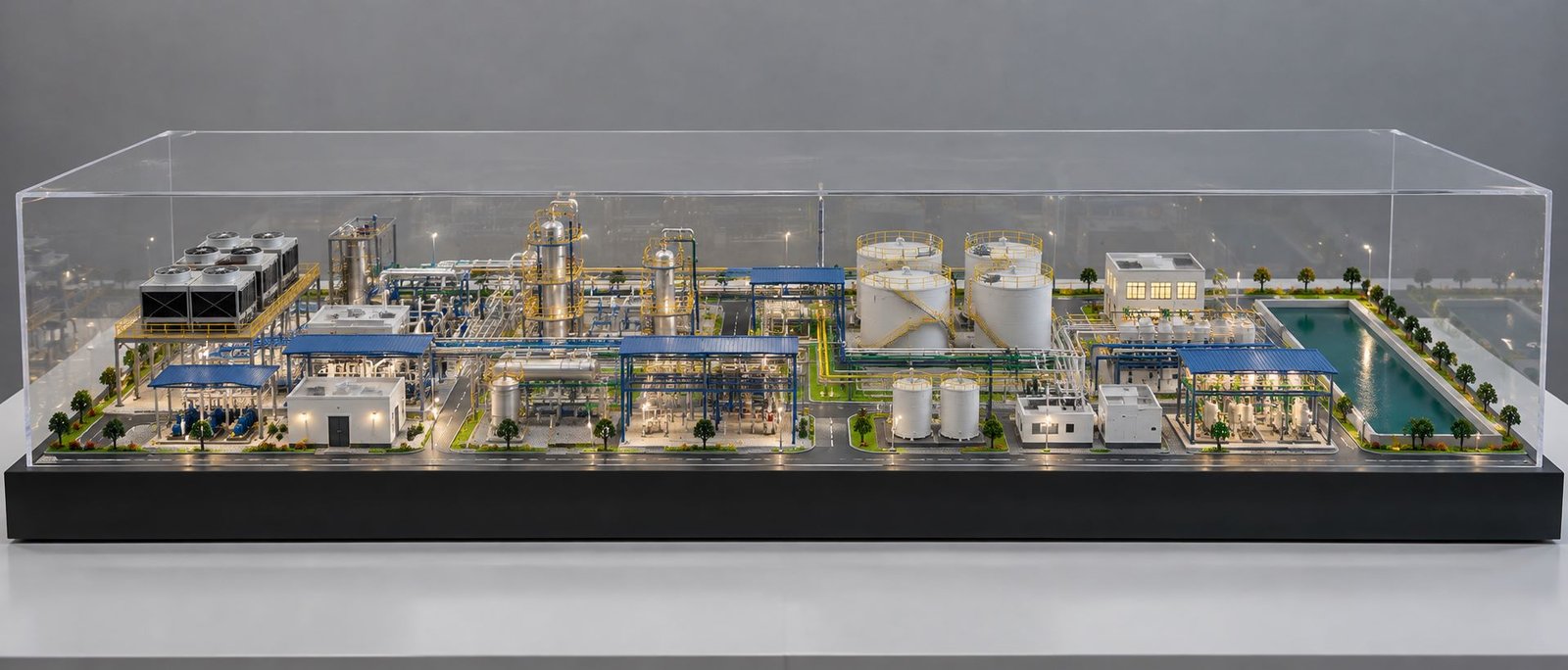
Industrial Compressor Working Model: Design, Components and Working Principle
An Industrial Compressor Working Model helps people understand how an industrial compressor system works. It shows the main equipment, piping connections, valves, pressure gauges, and other important components in one organised layout. As a result, engineers, students, project managers, and industrial clients can understand the system more easily.
Industrial compressors play an important role in manufacturing plants, workshops, power plants, processing facilities, and many other industries. They supply compressed air or gas to support different industrial operations. However, the complete system contains several components that may be difficult to understand from drawings alone. Therefore, a detailed scale model provides a clear visual explanation.
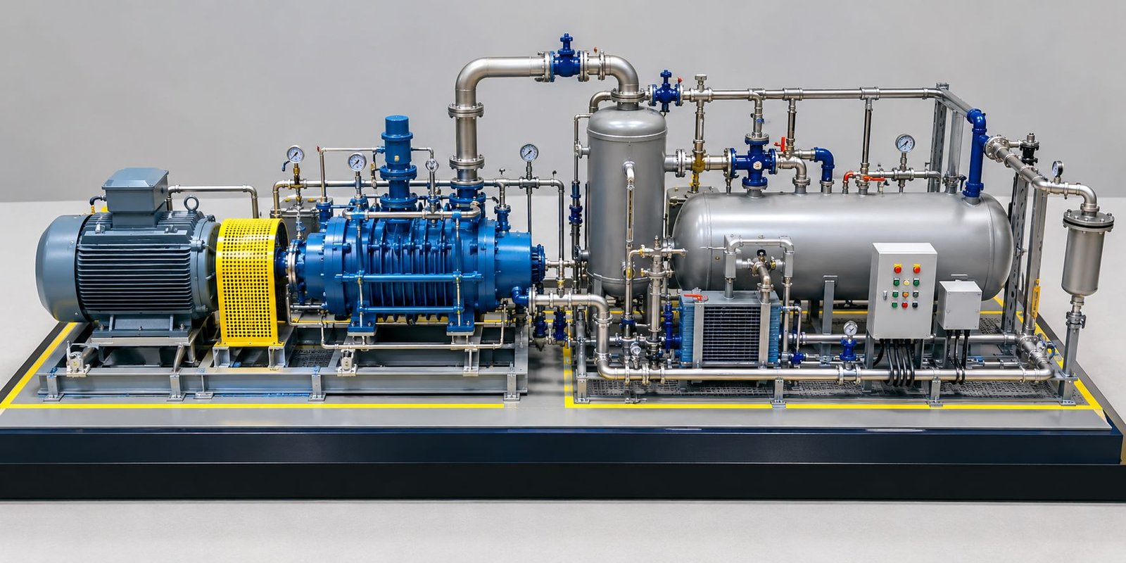
PAL Design Models creates custom industrial, engineering, and architectural scale models for technical presentations, exhibitions, and project visualisation. An Industrial Compressor Working Model can represent the actual equipment arrangement, including the compressor, motor, air receiver tank, piping, filters, cooling system, and control panel.
Depending on the project requirements, the model can feature realistic external details, colour-coded pipelines, equipment labels, and a professional display base. Furthermore, clients can choose a static display model or a functional demonstration model based on their objectives.
What Is an Industrial Compressor Working Model?
An Industrial Compressor Working Model is a physical representation of an industrial compressor system. It shows the main equipment and explains how the different components connect with one another.
For example, a typical compressed-air installation may include an electric motor, compressor unit, intake filter, cooling equipment, air receiver tank, pressure gauges, and connecting pipelines. The model presents these components in a compact arrangement so viewers can identify each part easily.
Moreover, the model can demonstrate the general path of air through the system. Arrows, labels, and colour-coded pipes help explain the direction of flow and the function of individual components.
The design depends on the purpose of the presentation. An educational model may focus on the basic compression process. In contrast, an industrial project model may show the equipment layout, support structures, pipe connections, and maintenance access.
A well-designed Industrial Compressor Working Model also improves technical communication. Instead of relying only on drawings or photographs, presenters can use the physical model to explain the equipment arrangement directly.
Working Principle of an Industrial Compressor Working Model
An industrial compressor draws in air or gas and increases its pressure using mechanical energy. The exact process depends on the compressor technology. However, most compressed-air systems follow a similar overall sequence.
First, the compressor draws air through an intake opening. An intake filter removes some dust and unwanted particles. Next, the compressor raises the air pressure. During this process, the air temperature usually increases.
Therefore, many installations use cooling equipment to manage the temperature. Some systems also require moisture separation, oil separation, or additional filtration before the air enters the distribution network.
After treatment, the compressed air may enter an air receiver tank. This tank stores compressed air and helps manage changes in demand. Finally, pipelines carry the air to the equipment that needs it.
An Industrial Compressor Working Model can represent this sequence through connected components, clearly marked pipelines, and suitable labels. Consequently, viewers can understand the basic operation without studying complicated technical drawings first.
Air Compression Process in an Industrial Compressor Working Model
The process starts when air enters the compressor through the intake filter. The compressor then uses mechanical energy to increase the air pressure.
For instance, a reciprocating compressor uses a piston, while a rotary screw compressor uses rotating screw elements. A centrifugal compressor uses a rotating impeller to increase the gas energy.
Although these technologies work differently, they all serve the purpose of increasing gas pressure.
After compression, the system may send the air through a cooler, separator, or filter. These components help prepare the air for its intended application. The system then stores or distributes the compressed air as required.
In a scale model, different components can show each stage of the process. In addition, colour-coded pipelines and flow arrows can help viewers follow the air path from the intake to the outlet.
Motor, Coupling and Compressor Operation
The electric motor provides the power needed to operate the compressor. Depending on the design, the motor transfers power through a coupling, belt, gear arrangement, or integrated drive.
A coupling connects the motor shaft to the compressor shaft. Meanwhile, a coupling guard covers the rotating connection and helps prevent accidental contact.
The scale model should show the motor and compressor in the correct relative positions. It should also include the mounting arrangement and coupling guard where applicable.
These details make the model more realistic. More importantly, they help viewers understand how the drive system connects to the compressor unit.
Main Components of an Industrial Compressor Working Model
A detailed Industrial Compressor Working Model may contain several mechanical, electrical, and piping components. However, the final selection depends on the actual equipment configuration and the required scale.
Compressor Unit and Electric Motor
The compressor unit forms the centre of the installation. It increases the pressure of air or gas for industrial use. Its shape and size vary according to the compressor type and manufacturer.
The electric motor supplies the required mechanical power. In a scale model, the motor may feature a detailed outer housing, ventilation openings, terminal box, and mounting feet.
Similarly, the compressor body can represent a reciprocating, rotary screw, or centrifugal design. Accurate proportions help viewers recognise the equipment and understand its relationship with the motor.
For presentation purposes, the model can also include equipment labels and manufacturer branding when the client provides the relevant details.
Skid Base and Coupling Guard
The skid base supports the compressor, motor, and associated equipment. Manufacturers often use a structural steel base to keep the components securely positioned.
A scale model can reproduce the base frame, support members, mounting points, and equipment arrangement. Depending on the reference design, it may also include lifting points and anchor locations.
The coupling guard provides another important detail. It represents the protective cover around the rotating connection between the motor and compressor.
By including these components, the model presents a more complete view of the compressor package. In addition, it helps explain the importance of equipment support and mechanical protection.
Air Receiver Tank and Pressure Gauges
An air receiver tank stores compressed air and helps balance variations between supply and demand. It can also provide time for some moisture to settle, although the system may still require separate moisture-removal equipment.
The tank may have a vertical or horizontal arrangement. Its visible details can include support legs, inlet and outlet connections, a pressure gauge, a safety valve, and a drain point.
Pressure gauges show the pressure at selected locations in the system. Therefore, the model should position them near the relevant equipment and connections.
The correct arrangement depends on the original installation. By following the reference drawings, the model-making team can reproduce the main features more accurately.
Piping, Valves and Air Filters
Pipelines connect the compressor to the receiver tank, treatment equipment, and distribution system. Their arrangement depends on the plant layout and the operating requirements.
A detailed model may include suction lines, discharge lines, drain lines, bends, flanges, and pipe supports. It may also show isolation valves, check valves, and other fittings.
Air filters remove contaminants from the compressed-air stream. Their position depends on the compressor design and the required air quality.
Furthermore, colour-coded pipes can help distinguish different flow paths. Labels and arrows make these connections easier to understand during a technical presentation.
Oil Separator and Lubrication System
Some compressors use oil for lubrication, sealing, and heat management. In these systems, an oil separator helps remove oil from the compressed air before the air continues downstream.
The lubrication system may include an oil reservoir, filter, cooler, and connecting lines. However, the exact arrangement varies between compressor designs.
A scale model can show the separator vessel, oil lines, and related components. As a result, viewers can understand how the supporting equipment connects to the main compressor.
It is important to note that not every compressor uses the same lubrication system. For example, oil-free compressors follow different arrangements. Therefore, the model should match the selected equipment rather than include components that do not belong to the actual system.
Cooling System and Heat Exchanger
Compression usually generates heat. For this reason, many industrial compressor installations include cooling equipment.
Depending on the design, the system may use cooling fans, water cooling, an intercooler, or an aftercooler. A heat exchanger transfers heat between fluids without directly mixing them.
In the scale model, the cooling section can include a heat-exchanger body, fan, connecting pipes, and relevant supports. These details help explain how the installation manages heat during operation.
Additionally, the model can use clear labels to distinguish the cooling equipment from the main compressor and air-treatment components.
Control Panel, Safety Valves and Drain System
The control panel allows operators to monitor and control the compressor. It may contain switches, indicator lights, displays, alarms, and other monitoring devices.
Safety valves help protect suitable pressurised equipment from excessive pressure when correctly selected and installed. Meanwhile, drain points remove accumulated condensate from receivers, filters, and other parts of the system.
A detailed model can include a control panel with representative buttons and indicators. It can also show safety devices and drain connections in their approximate positions.
Together, these features provide a clearer picture of the complete compressor installation.
Industrial Compressor Working Model Design and Scale Model Making
Creating an Industrial Compressor Working Model requires careful planning. The design should represent the major equipment accurately while keeping the layout easy to understand.
First, the model-making team reviews the available technical information. This information may include general arrangement drawings, equipment datasheets, photographs, piping layouts, CAD files, and dimensions.
Next, the team selects a suitable scale and determines the overall model size. The chosen scale should provide enough space to display important equipment and connections clearly.
After that, the team plans the base, component placement, pipe routing, colours, labels, and finishing details. This approach helps maintain a consistent appearance throughout the model.
Layout and Arrangement of Compressor Components
The layout determines how viewers see the compressor, motor, receiver tank, cooling equipment, and control panel.
For an existing industrial installation, the model should follow the supplied layout as closely as the chosen scale allows. For a conceptual presentation, the team can organise the components to improve visibility while maintaining the intended engineering relationships.
A display base may include a project title, equipment labels, and a small flow diagram. These additions make the model easier to explain during meetings and exhibitions.
Piping Connections and Equipment Placement
Piping often plays a major role in the appearance of an industrial compressor model. Poorly arranged pipework can make the entire system difficult to understand.
Therefore, the design should follow the reference drawings wherever possible. Important connections, bends, valves, flanges, and supports can be represented according to the required level of detail.
When the original layout contains many small pipes, the team may simplify selected details to improve visibility. However, the simplified arrangement should preserve the main flow paths and equipment relationships.
As a result, viewers can understand the installation more quickly and follow the system connections with greater confidence.
Material Selection for an Industrial Compressor Working Model
Material selection depends on the model size, required finish, fabrication method, and intended use.
For example, acrylic and plastics may suit certain housings and transparent sections. Resin and 3D-printed parts can reproduce complex shapes. Meanwhile, laser-cut components can help create panels, structural elements, and base details.
The team may also use miniature pipes, metal fittings, custom paint finishes, and printed labels to improve the final appearance.
For exhibition models, the base and individual components should remain secure during handling and transportation. Therefore, the team should consider strength, fixing methods, and protective packaging during the design stage.
Types of Industrial Compressor Working Models
Industrial compressors use different technologies to increase gas pressure. Each type has its own operating mechanism and equipment arrangement.
Reciprocating Compressor Working Model
A reciprocating compressor uses a piston that moves inside a cylinder. This movement changes the cylinder volume and compresses the gas before discharge.
A model can show the cylinder, piston assembly, connecting rod, crank mechanism, motor, and inlet and outlet connections.
This design works well for educational demonstrations because viewers can study the basic piston-based compression process. A cutaway or moving mechanism can provide additional detail when the project requires it.
Rotary Screw Compressor Working Model
A rotary screw compressor uses rotating screw elements to compress gas. Industries often use this type of compressor where they need a continuous supply of compressed air.
A model may include the compressor housing, motor, intake filter, oil separator where applicable, cooling equipment, and discharge piping.
Furthermore, the model can show the arrangement of the complete compressor package. If the presentation requires a view of the internal screw mechanism, the design may include a cutaway section or a separate explanatory component.
Centrifugal Compressor Working Model
A centrifugal compressor uses a rotating impeller to increase the energy of the gas. The compressor’s flow passages and diffuser then help convert that energy into a pressure rise.
A scale model can show the casing, impeller section, drive arrangement, inlet, outlet, and supporting equipment.
This type of model can support presentations involving large industrial plants, processing facilities, and power generation projects.
Applications of an Industrial Compressor Working Model
An Industrial Compressor Working Model supports a wide range of professional and educational activities. It makes the equipment arrangement easier to explain and gives viewers a physical reference during discussions.
Engineering and Industrial Project Presentations
Engineering teams can use compressor models to present equipment layouts, project proposals, and installation concepts. The physical model allows clients to see how the main components fit together.
Moreover, the team can add project-specific labels, colour-coded piping, and equipment identification to improve clarity.
Industrial Exhibitions and Trade Shows
At industrial exhibitions, a compressor scale model can attract visitors and explain a product or installation visually.
Unlike full-size equipment, a compact model fits comfortably on a display counter or exhibition stand. In addition, a professional finish can help manufacturers and engineering companies present their work effectively.
Educational Institutions and Technical Training
Engineering colleges, polytechnic institutes, and technical training centres can use compressor models to explain mechanical systems and industrial equipment.
A static model helps students identify individual components. Meanwhile, a functional demonstration model can explain selected operating principles when the design includes appropriate mechanisms and safety measures.
Manufacturing Plants and Equipment Manufacturers
Manufacturers can use scale models to present compressor packages and explain their equipment configurations.
Similarly, plant teams can use the models during internal discussions about equipment placement, piping arrangements, and maintenance access. However, the model should support approved engineering drawings rather than replace them.
Sales Meetings and Client Demonstrations
Sales and technical teams can use an Industrial Compressor Working Model to explain equipment features to prospective customers.
For example, the presenter can identify the compressor, motor, air receiver, filters, and cooling equipment while explaining the purpose of each component. Consequently, clients can understand the proposed installation more easily.
Benefits of an Industrial Compressor Working Model
A professionally designed compressor model provides several practical benefits.
Clear visualisation: The model brings the main equipment and connections together in one compact display.
Easier technical explanations: Labels, flow arrows, and colour-coded pipes help viewers understand the system.
Professional presentations: A physical model adds a visual element to engineering meetings, exhibitions, and client discussions.
Customised design: The team can create the model using project drawings, CAD files, dimensions, and reference photographs.
Reusable display: A durable model can support multiple presentations, training sessions, and exhibitions.
Better layout discussions: The model helps stakeholders visualise equipment placement and discuss design concepts.
However, the final result depends on the quality of the reference information, the selected scale, and the intended purpose. Therefore, clients should define their requirements before fabrication begins.
How to Choose an Industrial Compressor Working Model
Choosing the right model starts with identifying its purpose. For instance, an educational model may focus on the compression process, while an industrial presentation model may require realistic equipment and piping details.
First, confirm the compressor type and list the components that the model must include. Next, provide available drawings, photographs, CAD files, and equipment dimensions.
Then, decide whether you need a static model, an interactive model, or a functional demonstration. A static model focuses on appearance and layout. In comparison, an interactive model may include removable covers or movable parts. A functional model requires additional engineering and appropriate safety measures.
You should also consider the display size, material, paint finish, labels, colour scheme, and transportation requirements.
Finally, review the proposed layout before fabrication. This step helps identify missing details early and reduces unnecessary revisions later.
Custom Industrial Compressor Working Model by PAL Design Models
PAL Design Models provides custom scale model-making services for industrial, engineering, architectural, and project presentation requirements.
An Industrial Compressor Working Model can include a compressor unit, electric motor, skid base, coupling guard, air receiver tank, piping, pressure gauges, filters, valves, cooling equipment, and control panel. The team can adapt the level of detail to suit the selected scale and presentation objective.
Depending on the project, the model may use 3D-printed components, fabricated parts, miniature fittings, custom paint finishes, and equipment labels. Furthermore, the design can follow the client’s drawings, dimensions, photographs, and technical references.
Whether you need a model for an engineering presentation, industrial exhibition, training facility, or manufacturer demonstration, the design should communicate the equipment arrangement clearly.
To discuss your requirements, visit the official website:
Final Thought
An Industrial Compressor Working Model makes complex equipment easier to understand by showing the main components and their connections in one organised display. With a suitable scale, clear piping, realistic details, and accurate equipment placement, the model can support technical presentations, training, exhibitions, and project discussions. PAL Design Models can develop a customised industrial scale model based on your requirements and available technical references.