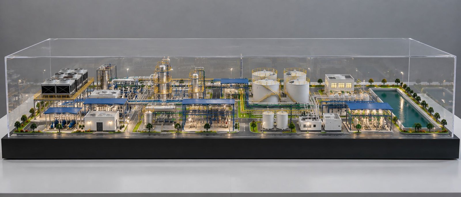
Pump and Motor Working Model: Working Principles Guide
A Pump and Motor Working Model is a physical working model that represents an industrial pumping system. The model demonstrates the relationship between mechanical power, fluid movement, valves, pressure indicators and control systems.
Unlike a basic display model, a working pump and motor model can demonstrate the actual working sequence. The motor provides rotational power to the pump, which creates the pressure needed to move water or another fluid through the piping system. Valves, pressure gauges and flow indicators can demonstrate changes within the system.
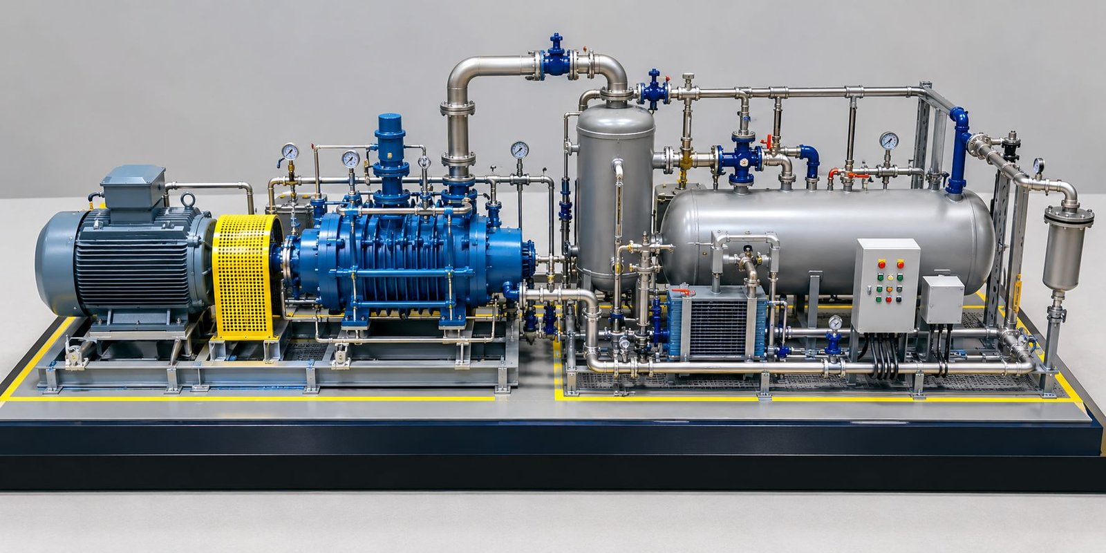
The working model is useful for engineering presentations, technical demonstrations, industrial training, exhibitions and project visualization. A detailed physical model can include a motor, pump, reservoir, suction and discharge piping, valves, pressure gauges, flow indicators, control panel, electrical connections and supporting structures.
What Is a Pump and Motor Working Model?
A Pump and Motor Working Model represents a real pumping system at a much smaller physical scale. The model combines mechanical and fluid systems into a single compact setup.
The electric motor provides mechanical energy to the pump. The pump then converts this mechanical energy into hydraulic energy and moves the fluid through the system.
For example, water can be stored inside a transparent tank. A suction pipe connects the tank to the pump and allows water to enter the pump. The pump then circulates the water through the discharge pipe.
The water can pass through valves, gauges, transparent flow sections and return piping before reaching the reservoir again. As a result, the model can demonstrate a complete working pumping cycle.
Main Components of the Pump Motor Working System
A professional pump motor working system can contain numerous interconnected components. Each component performs a specific function within the model.
Components of an Industrial Pump Working Model
The main components can include:
- Electric motor
- Centrifugal pump
- Coupling
- Coupling guard
- Water reservoir
- Suction pipe
- Discharge pipe
- Isolation valves
- Control valves
- Pressure gauges
- Flow indicator
- Transparent pipe section
- Pipe flanges
- Pipe supports
- Control panel
- Electrical wiring
- Base frame
- Safety markings
Additional components can be added according to the intended purpose and required level of detail of the model.
Electric Motor in a Pump and Motor Working Model
The electric motor acts as the driver for the pumping system. It converts electrical energy into mechanical rotational energy.
The physical model can use a miniature industrial motor or a suitable low-voltage motor for safe demonstration.
The motor typically connects to the pump through a coupling. When electrical power reaches the motor, its shaft rotates. The coupling then transfers this rotational power to the pump.
Therefore, the motor provides the primary mechanical energy required for the pumping process.
A detailed engineering working model can also demonstrate the motor housing, cooling fins, terminal box, mounting base and cable connection.
Pump Working Model and Its Role
The pump is the main hydraulic component of the system. Its primary role is to move fluid from one point to another.
A centrifugal pump can be used for many pumping applications. In a pump working model, the pump can connect the reservoir to the discharge piping.
When the pump rotates, its impeller transfers energy to the fluid. The fluid then moves through the discharge line.
As a result, the model can demonstrate the basic relationship between mechanical rotation and fluid movement.
How the Motor Drives the Pump
The motor and pump connect through a coupling. The coupling transfers the rotational movement of the motor shaft to the pump shaft.
The basic working sequence can be represented as:
Electrical Power → Motor Rotation → Coupling Rotation → Pump Impeller Rotation → Fluid Movement
This sequence is one of the main principles demonstrated by a Pump and Motor Working Model.
A coupling guard can cover the rotating connection for safety. It also gives the physical model a more realistic industrial appearance.
Working Principle of the Pumping System
The working process begins with the reservoir. Water remains stored inside the tank before the model starts.
When the operator activates the control switch, electrical power reaches the motor. The motor begins to rotate and transfers its motion to the pump.
The pump draws water through the suction pipe. The impeller inside the pump transfers energy to the water and pushes it through the discharge pipeline.
The water then travels through the connected valves, flow indicators and other piping components. Finally, the water returns to the reservoir.
As a result, the same water can continue circulating through the system during a demonstration.
This closed-loop configuration is useful for a pumping system working model because it allows continuous operation without requiring a large quantity of water.
Suction System in an Industrial Pump Working Model
The suction system connects the reservoir to the pump inlet. This section plays an important role because the pump requires a suitable fluid supply before it can operate correctly.
The model can demonstrate a suction pipe, isolation valve, strainer and flange connections.
Additionally, a transparent section can be incorporated into the suction line. This allows viewers to observe fluid movement.
The suction line can also include a pressure gauge or vacuum indicator when the industrial pump working model requires more advanced features.
Discharge System of the Pump Motor Model
The discharge system transports fluid away from the pump.
It can include a discharge pipe, control valve, pressure gauge, flow meter and return line. A pressure gauge on the discharge side can demonstrate the discharge pressure.
Opening or closing the control valve changes the resistance within the system. This provides an opportunity to demonstrate the relationship between flow restriction and pressure.
For example, partially closing a control valve can restrict the flow. The operator can then observe the corresponding response on the flow indicator or pressure gauge.
Role of Valves in a Pump Working Model
Valves are essential components of industrial pumping systems. They can control, isolate or regulate fluid movement.
A pump working model can demonstrate different types of miniature valves.
Isolation Valves
Isolation valves can demonstrate how a particular section of the pipeline can be opened or closed.
Control Valves
Control valves can demonstrate how the flow through the system can be regulated.
Check Valves
Check valves can demonstrate one-way fluid movement within the piping system.
In addition, hand-operated valves can make the model more interactive because the operator can physically change the flow condition during a demonstration.
Pressure Gauge Demonstration in a Pump Motor Working System
Pressure gauges provide a visual indication of pressure within the piping system.
A professional pump motor working system can include pressure gauges on the suction and discharge sides. Their positions should reflect the actual system layout.
During pump operation, the discharge side can demonstrate higher pressure compared with the suction side.
Therefore, pressure gauges can help explain an important function of the pump: creating the pressure difference required to move fluid through the system.
For a display model, miniature functional gauges can be used where applicable. Alternatively, representative gauges can be installed for visual demonstration.
Flow Indicator in a Pump and Motor Model
A flow indicator allows viewers to understand whether fluid is moving through a particular section of the pipeline.
A transparent flow tube can make the fluid movement easier to observe. When water passes through the transparent section, its movement becomes visible.
As a result, viewers do not have to depend only on the sound or vibration of the pump. The movement of the fluid itself becomes part of the visual demonstration.
A flow meter can also be added to more advanced pump and motor working models.
Transparent Water Reservoir for Pump Working Models
A transparent reservoir can improve the educational value of the physical model.
Viewers can see the water level inside the tank and follow the return flow. The tank can have a suction connection at the lower section and a return connection at the upper section.
Furthermore, an internal strainer or perforated section can demonstrate the suction arrangement.
The transparent reservoir also improves the presentation value of the engineering pump working model during exhibitions and technical presentations.
Pipe and Flange Detailing in an Industrial Pumping Model
Industrial piping contains numerous connections, supports and fittings. Therefore, a detailed industrial pumping model should include more than simple pipe sections.
Piping Components for a Working Engineering Model
The model can include:
- Flanges
- Elbows
- Tees
- Reducers
- Valves
- Pipe supports
- Bolts
- Gaskets
- Pressure gauges
- Flow indicators
These small details improve the realism of the physical model.
In addition, proper alignment of the pipe supports improves the technical appearance of the complete installation.
Control Panel for a Pump and Motor Working Model
A control panel can operate the motor and other electrical features of the model.
A basic panel can include an ON/OFF switch, indicator lights and an emergency stop control.
More advanced models can include digital displays and motor speed controls.
The control panel can be mounted on the side of the base frame so that the piping remains clearly visible.
For example, a green indicator can show that the system is running, while another indicator can represent power availability.
Electrical Wiring in the Pump Motor System
Electrical wiring connects the motor, control panel and other working components.
In a professional physical model, wires should remain tidy and safely routed. Cable trays or conduits can also represent the electrical installation.
The wiring can run underneath the baseboard or through dedicated channels.
As a result, the pump motor system can maintain a clean appearance while still demonstrating realistic industrial detailing.
Base Frame and Industrial Structure
The complete pump and motor assembly should sit on a sturdy and visually clean base frame.
A rectangular industrial platform can support the motor, pump, reservoir and piping.
The frame can feature mounting brackets, support beams, anchor bolts and equipment foundations.
A continuous rectangular baseboard can also improve the overall presentation of the industrial working model. Yellow or contrasting safety markings can define equipment zones and walkways.
Coupling and Coupling Guard in a Pump Working System
The coupling connects the motor shaft to the pump shaft. It is an important mechanical component because it transfers rotational power.
The model can demonstrate the coupling while protecting the rotating part with a coupling guard.
The guard also represents an important industrial safety feature.
Therefore, the coupling section can demonstrate how mechanical energy transfers from the motor to the pump.
Complete Working Sequence of the Pump and Motor Model
The complete operation can be demonstrated through a simple sequence.
First, water remains inside the reservoir. The operator checks that the valves are in the required positions.
Next, the control panel supplies power to the motor. The motor begins to rotate.
The coupling transfers the motor’s rotation to the pump shaft. The pump impeller then begins moving the water.
The pump draws water through the suction pipe and pushes it into the discharge line.
The water then passes through the connected valves, gauges and flow indicators.
Finally, the water returns to the reservoir through the return line.
Because of the closed-loop arrangement, the Pump and Motor Working Model can demonstrate the pumping cycle for an extended period, subject to the equipment and operating conditions.
Demonstrating Flow Control with a Pump Working Model
One of the most useful features of a pump working model is flow control.
The operator can adjust a control valve and observe the response of the system.
When the valve is fully open, the system can demonstrate the maximum flow under suitable operating conditions. When the valve is partially closed, the system experiences increased resistance in the flow path.
As a result, the model can demonstrate how valves influence the operation of the pumping system.
This feature is particularly useful for technical training and engineering presentations.
Demonstrating Pump Pressure
The model can also demonstrate pressure differences between different points in the system.
A discharge pressure gauge can indicate the pressure created by the pump. Another pressure gauge can be installed on the suction side where applicable.
The operator can observe how pressure changes with different operating conditions.
Furthermore, this setup can demonstrate the relationship between pump operation, system resistance and fluid movement.
Motor Speed and Pump Operation
Advanced pump and motor working models can include a speed controller to vary the motor speed.
Changing the motor speed can change the pump operating conditions. This allows the presenter to demonstrate how motor operation influences the pumping system.
However, the motor, pump and control system should be selected so that they operate within their designated operating range.
For physical demonstration models, safe low-voltage components and appropriate protective arrangements should be used where applicable.
Industrial Detailing in the Physical Working Model
The appearance of the model is important because the objective is to represent a real engineering installation.
Detailed elements can include equipment labels, pipe supports, flanges, bolts, cable trays, control boxes, gauges and safety markings.
The motor and pump should have realistic proportions. The pipes should follow a logical arrangement instead of appearing as decorative elements.
Furthermore, the equipment should remain accessible enough for viewers to understand the working principle.
3D Printing for Pump and Motor Models
3D printing can assist in creating customized components for detailed engineering models.
Small valve bodies, brackets, pipe fittings, equipment housings, control components and other complex parts can be fabricated using 3D printing.
Additionally, unique components can be reproduced according to project drawings.
This technique becomes particularly valuable when the pump working model requires components that are difficult to fabricate manually at a small scale.
Laser Cutting for Engineering Working Models
Laser cutting can create accurate base plates, equipment brackets, control panel sections and structural elements.
It can also assist in producing repeated components with uniform dimensions.
Therefore, laser cutting and 3D printing can work together with traditional fabrication techniques to create a highly detailed engineering working model.
Applications of Pump and Motor Working Models
Pump and Motor Working Models can have several applications.
They can support:
- Engineering education
- Industrial training
- Technical presentations
- Exhibitions
- Project demonstrations
- Client meetings
Engineering teams can use these models to explain equipment layouts. Educational institutions can use them to demonstrate pumping principles.
Similarly, industrial exhibitions can use illuminated physical models to attract visitors and explain equipment functions.
Benefits of a Pump and Motor Working Model
A Pump and Motor Working Model makes technical concepts easier to understand.
Instead of looking at a static diagram, the audience can observe the actual working sequence.
The model can demonstrate mechanical rotation, fluid movement, valve operation and pressure changes.
Furthermore, the physical format allows viewers to examine the equipment arrangement from different angles.
The model also provides a useful reference for technical discussions because the presenter can directly point to individual components.
Static Industrial Model vs Working Pump Model
A static industrial model focuses mainly on appearance and layout. It can show equipment, piping and structures without moving or functional components.
A working pump model adds an operational aspect. The motor can run, the pump can circulate water and the control panel can operate the system.
Therefore, the working model can communicate both the physical arrangement and the basic working principle.
This makes it particularly useful when a project requires a technical explanation.
Safety Considerations for Pump Motor Working Models
Safety should remain an important consideration when building a pump motor working model.
Electrical components should have appropriate protection. Rotating shafts and couplings should have guards.
Water and electrical connections should remain adequately separated. The model should use components suitable for its scale and operating requirements.
Furthermore, the operator should follow the manufacturer’s instructions for the actual pump, motor and electrical equipment used in the model.
Conclusion
A Pump and Motor Working Model provides a detailed physical representation of a pumping system and demonstrates the relationship between mechanical power and fluid movement.
The motor produces rotational power, while the coupling transfers this power to the pump. The pump moves water through the suction and discharge piping. Valves control the flow, pressure gauges indicate system conditions and a flow indicator helps demonstrate fluid movement.
A detailed physical model can also incorporate a transparent tank, industrial piping, flanges, valves, gauges, pipe supports, electrical wiring, control panels and safety features. These details improve the value of the model as a technical presentation tool.
A working model can demonstrate the complete working sequence. Water moves from the reservoir to the pump, travels through the discharge system and returns to the reservoir.
As a result, viewers can understand the complete pumping cycle through a physical demonstration rather than relying only on a drawing.
The combination of mechanical components, fluid flow, electrical controls and detailed industrial fabrication makes this type of engineering working model suitable for engineering presentations, industrial training, exhibitions and technical demonstrations.