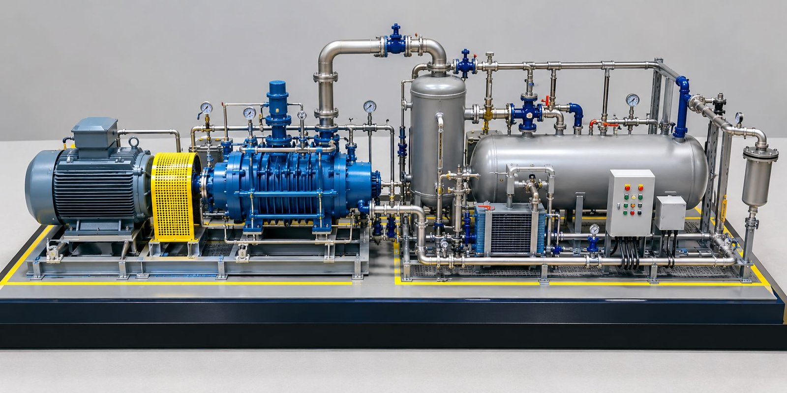
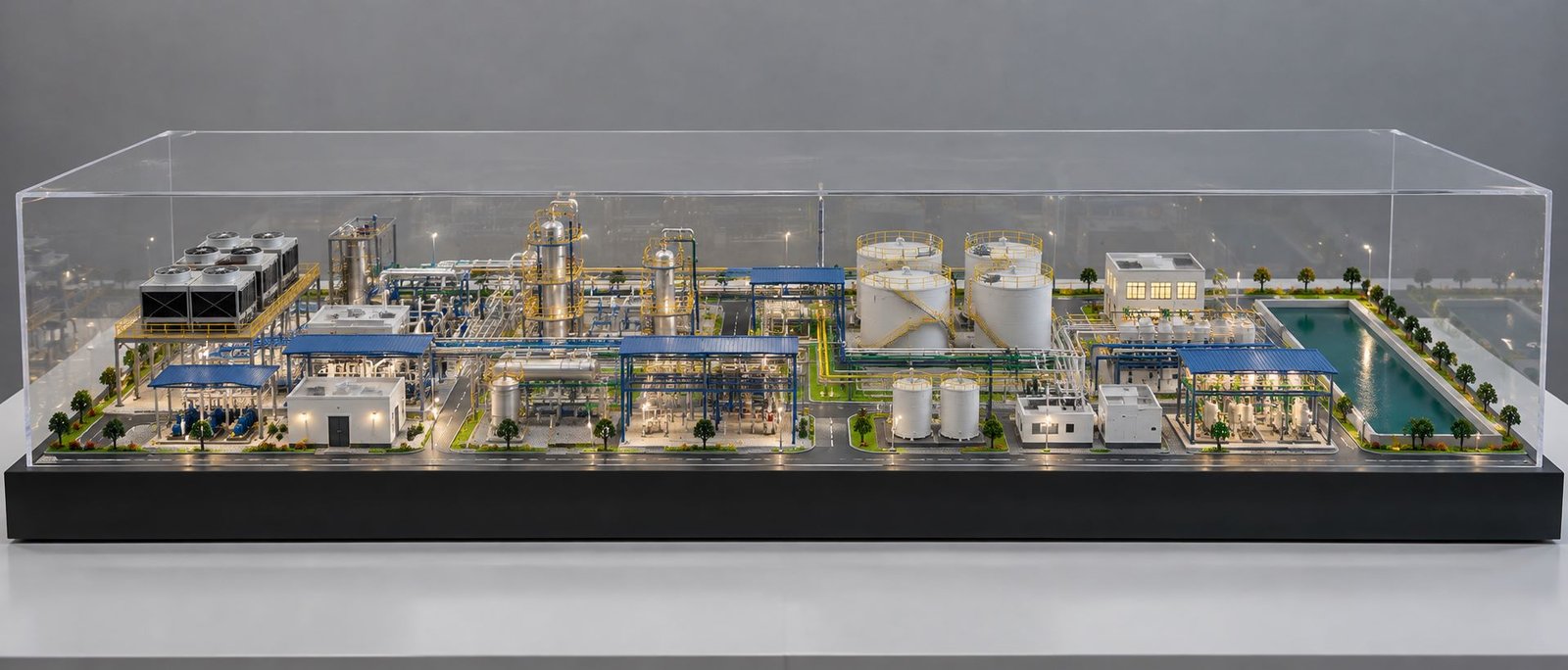
Anyone who has sat through a plant design review knows how quickly a piping and instrumentation diagram can turn into an unreadable maze of lines and symbols once a facility grows past a certain size. Even experienced engineers sometimes struggle to picture how a congested pipe rack will actually look once it’s built. That’s usually the point where someone suggests building a physical piping model, and it’s rarely a wasted suggestion. Seeing pipe runs, valves, and supports laid out in three dimensions tends to surface problems that stayed invisible on a flat drawing for weeks.
Why Physical Models Still Win Client Buy-In
Client presentations are another place a physical build earns its cost back quickly. Walking an investor or plant owner through a scaled piping model tends to build confidence in a proposal far faster than scrolling through isometric drawings on a laptop screen, simply because it lets someone unfamiliar with piping symbols still understand what they’re looking at. Sales and business development teams at EPC firms have caught on to this, which is part of why these builds keep showing up at project kickoff meetings and investor reviews well beyond their original engineering purpose.
A Reference That Outlasts the Original Project
A well-built piping model rarely gets retired once construction wraps up. Plant operators often keep it on hand for operator training long after commissioning, since walking a new hire through a scaled unit remains one of the fastest ways to build genuine familiarity with a plant’s layout.
Why 2D Drawings Struggle With Piping Complexity
Piping design is inherently spatial. A line that looks perfectly clear on an isometric drawing can turn out to clash with a structural beam, an electrical tray, or another pipe run once everything is actually routed through the same congested space. Engineers catch some of these conflicts through software-based clash detection, but not every clash gets flagged automatically, especially when drawings from different disciplines aren’t fully synchronised. A physical model closes that gap by forcing every route to exist in the same coordinate space at once, which tends to expose conflicts that software alone quietly misses.
What Goes Into an Accurate Industrial Piping Model
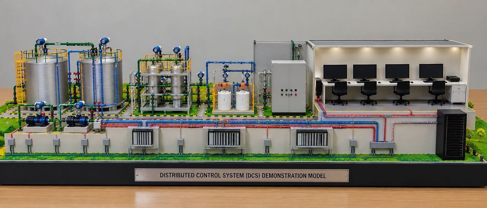
Scale and detail matter enormously here. A proper industrial piping model needs to represent pipe diameters, valve types, flange locations, and support spacing with enough accuracy that an engineer could genuinely use it to verify clearances, not just admire the layout. This level of precision is what separates a useful engineering tool from a display piece that merely looks impressive from across a room.
Getting there usually means working from the same isometric drawings, line lists, and equipment layouts that guide actual construction. A well-built industrial piping model reflects pipe schedules and insulation thickness accurately enough that maintenance teams can use it later to plan access routes for valve servicing, something a flat drawing rarely communicates well.
Fabrication tolerances get checked this way too. Support spacing that looks fine on a drawing sometimes turns out to leave a pipe under-supported once its actual weight and thermal expansion are accounted for, and reviewing a built model alongside the stress analysis gives engineers a far more intuitive sense of whether a support layout will actually hold up in practice.
Where a Plant Piping System Model Earns Its Keep
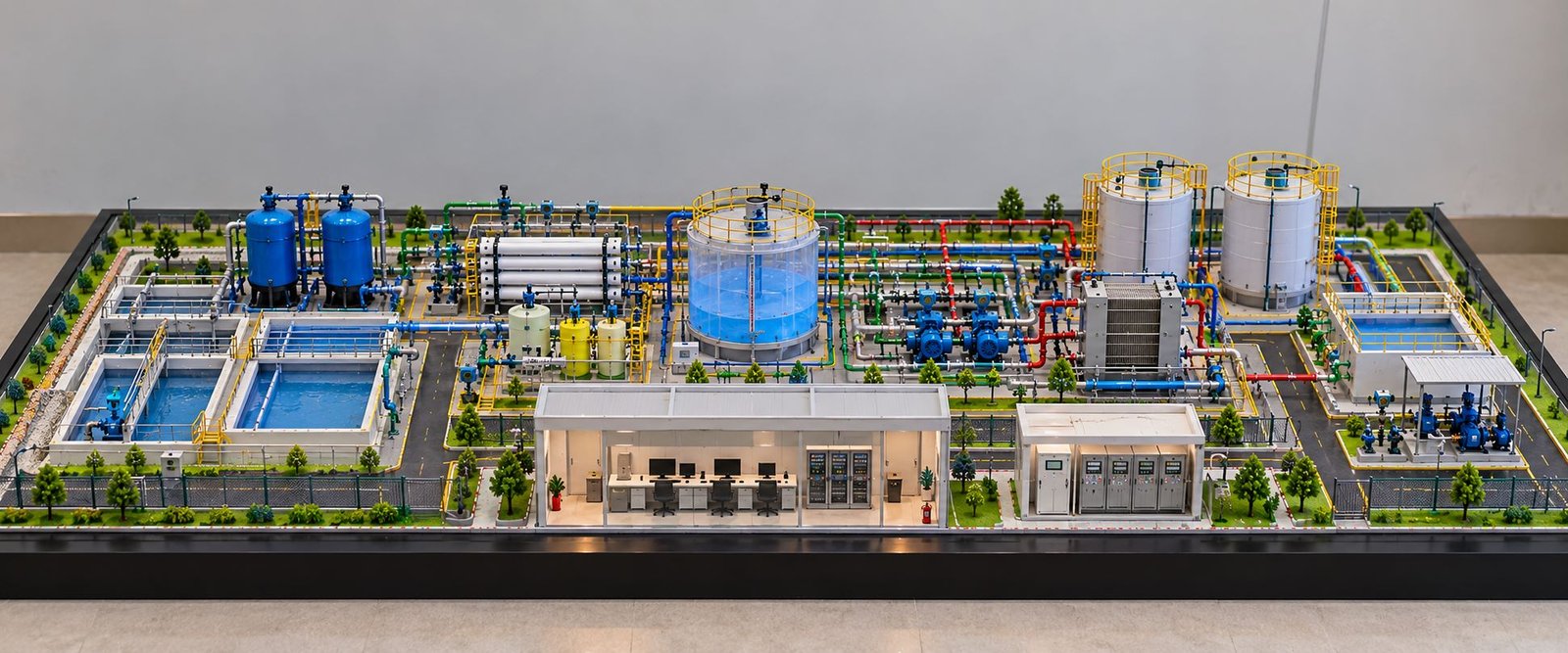
For process plants — refineries, chemical units, pharmaceutical facilities — piping congestion is often the single hardest thing to plan around. A plant piping system model lets engineers walk through a proposed unit before a single foundation is poured, checking whether there’s genuinely enough room for a technician to reach an isolation valve or whether a scaffold can be erected safely during a future shutdown. These are exactly the kinds of questions that are nearly impossible to answer confidently from a drawing alone.
Safety training is another place these builds prove their worth. New operators and maintenance staff learn a plant’s layout far faster by walking through a scaled plant piping system model than by studying a stack of isometric drawings, since the model lets them physically trace a line from a pump to a reactor and understand the process flow the way they’ll eventually experience it on the actual unit.
Shutdown and turnaround planning benefits from the same approach. Maintenance teams reviewing a plant piping system model ahead of a scheduled outage can plan crane positions and work sequencing far more confidently than they could from drawings alone, since the model shows exactly what obstacles they’ll be working around on site.
Catching Expensive Mistakes Before They Happen
Rework on an installed pipe rack is never cheap. Cutting and re-routing pipe after supports and hangers are already welded in place can delay a project by weeks, particularly if the change affects insulation, tracing, or instrumentation tie-ins along the same run. A physical model surfaces these conflicts while a design change still costs a few hours of rework rather than a full shutdown. Contractors who build a scaled industrial piping model early tend to walk into construction with far fewer surprises, and fewer surprises almost always translates into a project that finishes closer to schedule.
Choosing a Workshop That Understands Piping Engineering
Not every general model-making shop is equipped for this kind of detail. Piping work demands a team that can read isometric drawings fluently, understands pipe support standards, and knows how to represent valve types and instrumentation accurately rather than approximating them. Before commissioning a build, it’s worth asking to see prior piping and plant model work specifically, since this discipline differs meaningfully from architectural or structural modelling.
Turnaround time deserves attention too. Detailed piping builds with hundreds of fittings can take several weeks from drawing handoff to final assembly, so looping in a model maker early, while isometrics are still being finalised, tends to produce a far more useful build than rushing one together right before a client review.
Software has made piping design faster and more precise in many respects, but it hasn’t fully solved the problem of communicating a congested three-dimensional layout to a room full of people with different levels of technical background. A well-built model still does that job better than almost anything else available, which is exactly why so many EPC firms and plant owners keep commissioning them long after the drawings are already finished.