LNG Terminal Scale Model Making for Industrial Plant Presentations
Introduction to LNG Terminal Scale Model Making
An LNG Terminal Scale Model provides a detailed, three-dimensional view of a Liquefied Natural Gas terminal. It shows how storage tanks, processing units, pipelines, marine facilities, and supporting infrastructure work together within an industrial site. Moreover, it helps project owners, engineering consultants, EPC contractors, and energy companies present complex industrial projects in a clear visual format.
Liquefied Natural Gas (LNG) plays an important role in the global energy industry. Companies cool natural gas to extremely low temperatures to convert it into liquid form. This process reduces its volume and makes transportation by specialized LNG carrier ships more practical. At the receiving terminal, operators store the LNG and may convert it back into gas before sending it through transmission pipelines.
An LNG terminal contains several interconnected systems. These systems include LNG storage tanks, unloading facilities, transfer pipelines, pumps, regasification equipment, control buildings, utility areas, and safety infrastructure. Therefore, project teams need a clear way to present the complete facility and explain its layout.
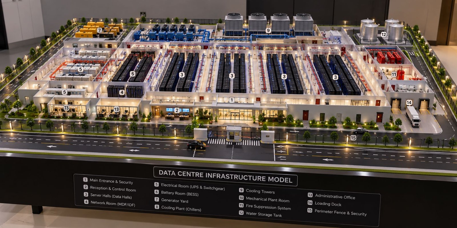
A professionally fabricated LNG Terminal Scale Model brings these elements together on a physical display base. It allows viewers to examine the plant from different angles and understand the relationship between individual equipment groups. In addition, the model gives technical presentations a practical visual reference.
PAL Design Models offers custom industrial scale model making services for engineering plants, infrastructure projects, and industrial presentations. A well-planned LNG terminal model can support project reviews, exhibitions, corporate presentations, and technical demonstrations.
What Is an LNG Terminal Physical Model?
An LNG terminal physical model represents an actual or proposed LNG facility in miniature form. It reproduces the main structures, equipment positions, pipe routes, storage areas, access roads, and marine facilities according to the project’s design requirements.
Unlike a flat drawing, a physical model displays height, depth, shape, and spatial relationships. For example, viewers can see how storage tanks connect with the process area, how pipe racks cross the plant, and how the unloading jetty connects the terminal with an LNG carrier.
The model maker can create a simplified layout or a highly detailed industrial presentation model. A conceptual model focuses on the complete site arrangement. In contrast, a detailed model may include miniature ladders, platforms, structural supports, equipment housings, pipe bends, valves, and access walkways.
Furthermore, the design can represent an LNG import terminal, export terminal, floating storage and regasification unit facility, or terminal expansion project. The selected components depend on the actual project scope.
Main Components of an LNG Terminal Scale Model
LNG Storage Tanks
LNG storage tanks form one of the most prominent sections of a typical LNG terminal. These tanks hold liquefied natural gas at cryogenic temperatures until the facility transfers or processes the product.
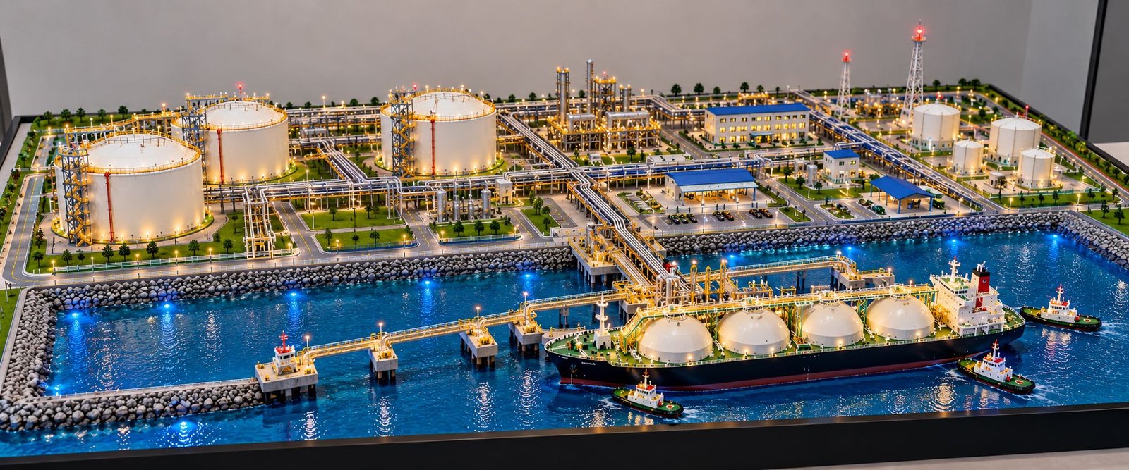
A detailed industrial scale model can feature large cylindrical tanks, domed roofs, tank foundations, external stairways, access platforms, railings, and connecting pipelines. The model maker selects suitable materials and finishes to reproduce the appearance of the reference structures.
The number and arrangement of the tanks depend on the project drawings. Therefore, accurate dimensions and proper spacing help maintain the overall layout.
Additionally, the model can include smaller utility tanks and associated equipment wherever the reference design requires them. These components add detail without distracting viewers from the main storage facilities.
LNG Carrier Ship and Marine Facilities
Many LNG import terminals receive LNG through specialized carrier ships. As a result, the marine area often becomes a major visual feature of the physical model.
A miniature LNG carrier can include a detailed hull, deck structures, cargo containment features, navigation bridge, railings, and supporting equipment. The ship should match the selected scale and sit correctly beside the unloading jetty.
The jetty can include structural columns, access walkways, unloading arms, mooring points, platforms, and connecting pipework. Meanwhile, the surrounding harbor can feature deep-blue water, breakwaters, shoreline protection, and service vessels.
These details help viewers understand how the terminal connects with maritime transportation infrastructure.
LNG Unloading System
The LNG unloading system transfers liquefied natural gas from the carrier to the terminal’s storage facilities. It usually includes marine unloading arms, cryogenic transfer lines, support structures, and related equipment.
A professional LNG terminal model should show these components clearly. Miniature pipes, metallic finishes, support frames, and connecting structures help reproduce the industrial appearance.
Furthermore, the unloading equipment should align with the ship and jetty arrangement. This alignment improves the model’s visual accuracy and makes the transfer area easier to understand.
Regasification Process Area
An LNG import terminal may convert liquefied natural gas into gaseous natural gas before sending it to a transmission pipeline. This process takes place in the regasification area.
Depending on the selected technology, the area may contain vaporizers, pumps, heat exchangers, process manifolds, metering equipment, and utility connections.
The physical model can represent these components with miniature vessels, equipment frames, pipe racks, platforms, and access routes. In addition, clear spacing between equipment groups helps viewers identify the main process areas.
The model maker should follow the project drawings wherever possible because different terminals use different process configurations.
Industrial Piping and Pipe Racks
Industrial piping connects storage tanks, pumps, process equipment, marine facilities, and gas transfer systems. Consequently, pipework plays a major role in the appearance of an LNG terminal scale model.
A detailed model may include multiple pipe sizes, horizontal and vertical runs, pipe bends, support brackets, and elevated pipe racks. Small rods or suitable miniature tubing can reproduce the main routes.
Moreover, the model maker can use project-approved colors to distinguish selected piping systems. However, the team should follow the client’s specifications instead of applying arbitrary color codes.
Well-arranged pipework creates a realistic industrial appearance while keeping important equipment visible.
Gas Export Pipeline and Metering Station
After regasification, natural gas may pass through metering and pressure-control facilities before entering a transmission pipeline.
The model can include the gas export pipeline, valve arrangements, metering equipment, support structures, and pipeline corridor. These elements help explain how the terminal connects with the wider gas network.
Furthermore, the designer can represent the terminal boundary and the route toward the external pipeline connection. The final arrangement should match the approved project layout.
Control Room and Administrative Buildings
Control rooms and administrative buildings support the daily operation of an LNG terminal. The site may also contain electrical rooms, maintenance workshops, security buildings, and other support facilities.
The model maker can fabricate these structures with acrylic sheets, MDF, plastics, or other suitable materials. Miniature doors, windows, roofs, staircases, and external finishes add realistic detail.
In addition, access roads, parking areas, pedestrian routes, and boundary walls help organize the site. These features make the overall plant layout easier to understand.
Flare Stack and Vent Structures
Some LNG facilities include flare systems, vent stacks, or other gas-handling structures, depending on their process design.
When the project requires them, the physical model can feature tall support towers, access platforms, ladders, structural frames, and connecting pipework.
These structures add height variation to the model and help represent the approved plant arrangement. However, the model maker should include only the systems supported by the project references.
Fire Protection and Safety Infrastructure
Fire protection and emergency access systems form an important part of industrial site planning. Depending on the facility, the model may include firewater tanks, pump houses, hydrant points, firewater pipelines, emergency access roads, and designated safety areas.
These elements help demonstrate how the terminal organizes its supporting infrastructure around the main process equipment.
Moreover, a detailed model can show access routes and selected safety-related structures without overcrowding the display. The physical model remains a presentation tool and does not replace formal safety studies or engineering calculations.
Importance of LNG Terminal Scale Models
Better Visualization of Complex Industrial Projects
Large LNG facilities contain many interconnected components. Two-dimensional drawings can communicate dimensions and technical information, but some viewers may find it difficult to understand the complete site arrangement.
A three-dimensional physical model presents the major components together. Therefore, project teams can explain storage areas, process units, roads, pipe racks, and marine facilities more clearly.
Improved Engineering Presentations
A professionally fabricated LNG Terminal Scale Model can become the central feature of a technical presentation. Project owners and consultants can use it to explain the proposed facility during meetings, reviews, and exhibitions.
Furthermore, the model gives presenters a shared visual reference. They can point to specific structures and explain their purpose without relying entirely on technical drawings.
Better Communication Between Project Teams
LNG projects involve process engineers, mechanical engineers, civil engineers, electrical specialists, instrumentation teams, and construction planners.
A physical model allows these teams to view the complete facility in one place. As a result, they can discuss equipment locations, access routes, and relationships between different plant areas more easily.
However, teams should continue to use approved engineering documents for detailed coordination and design decisions.
Support for EPC Contractors
Engineering, procurement, and construction contractors often present complex projects to clients and management teams. An industrial plant scale model can help communicate the project’s overall arrangement and infrastructure requirements.
Additionally, EPC contractors can combine the model with project drawings, process diagrams, and technical presentation panels to create a more informative display.
Industrial Exhibitions and Corporate Displays
Energy exhibitions and industrial trade shows provide opportunities to present engineering projects to a wider audience. A detailed LNG terminal model can attract attention while demonstrating the main components of the facility.
A wide-format display base can show the industrial site and marine area together. Meanwhile, realistic surface finishes and suitable lighting can improve visibility without hiding the model’s finer details.
Types of LNG Terminal Scale Models
LNG Import Terminal Model
An LNG import terminal model focuses on facilities that receive liquefied natural gas from carrier ships. It may include storage tanks, unloading jetties, transfer pipelines, regasification equipment, metering stations, and gas export connections.
This model type suits projects that need to demonstrate LNG receiving and distribution infrastructure.
LNG Export Terminal Model
An LNG export terminal model represents facilities that prepare natural gas for liquefaction, storage, and shipment.
Depending on the project, the model may include gas treatment equipment, liquefaction trains, refrigeration systems, LNG storage tanks, loading jetties, and marine infrastructure.
Export terminals often contain extensive process equipment. Therefore, the model maker should review the project layout carefully before selecting the scale and fabrication details.
Floating Storage and Regasification Unit Model
A Floating Storage and Regasification Unit (FSRU) is a specialized vessel that stores LNG and converts it back into gas. A model of an FSRU terminal can include the vessel, mooring arrangements, marine connections, and shore-based pipeline infrastructure.
This configuration differs from a conventional land-based terminal. Consequently, the physical model should clearly distinguish the floating facility from the shore-based equipment.
LNG Terminal Expansion Model
An expansion model shows proposed additions to an existing LNG terminal. These additions may include new storage tanks, extended pipe racks, extra process units, utility installations, and revised access routes.
Moreover, the model maker can distinguish existing structures from proposed additions through approved colors or presentation features.
Conceptual LNG Infrastructure Model
A conceptual LNG terminal model focuses on the major equipment groups and the overall site arrangement. It does not necessarily reproduce every pipe, valve, or small structural component.
This approach works well for early-stage planning and preliminary presentations. It also allows project teams to communicate the general concept before they finalize every engineering detail.
Materials Used in LNG Terminal Model Making
Acrylic Sheets
Acrylic sheets work well for transparent covers, selected building components, windows, and display enclosures. Clear acrylic can also protect delicate model components during transportation and exhibition.
ABS and Engineering Plastics
ABS sheets, rods, and tubes help model makers create tanks, equipment housings, pipelines, supports, and other industrial components. These materials offer flexibility for cutting, shaping, assembling, and finishing miniature parts.
MDF and Plywood
MDF and plywood provide a strong foundation for display bases and selected structural components. The model maker chooses the appropriate thickness according to the model’s dimensions and weight.
Furthermore, a properly finished base helps organize the site layout and supports safe transportation.
Metal Components
Metal rods, wire, mesh, and other small metal parts can reproduce railings, ladders, structural supports, and selected equipment details.
These materials work particularly well when a component needs a thin profile or additional strength.
3D-Printed Components
3D printing allows model makers to produce complex shapes, miniature equipment housings, pump assemblies, valves, fittings, and custom components.
CAD-based fabrication also helps reproduce repeated parts consistently. After printing, the team can sand, paint, and finish the components to match the overall model.
Paint Finishes and LED Lighting
Industrial colors help distinguish tanks, equipment, buildings, pipelines, roads, and utility areas. Consistent finishing also improves the overall presentation quality.
Additionally, LED lighting can highlight selected tanks, buildings, process units, and marine facilities. The lighting arrangement should improve visibility and preserve the natural appearance of the physical model.
LNG Terminal Scale Model Making Process
Project Brief and Reference Drawings
First, the model-making team reviews the project requirements and identifies the main components. The client may provide plot plans, general arrangement drawings, CAD files, equipment layouts, reference photographs, and approved three-dimensional designs.
These references help the team understand the facility’s overall arrangement and determine the required level of detail.
Scale Selection and Layout Planning
Next, the team selects a suitable scale according to the terminal’s footprint, display area, and presentation purpose.
A large terminal may require a smaller scale to fit the complete facility on one baseboard. Conversely, a selected process area may need a larger scale to show individual equipment details clearly.
The team should balance the overall plant layout with the visibility of important components.
CAD Design and Component Planning
CAD tools help establish the model dimensions, tank positions, equipment locations, road layouts, and pipe rack alignments.
Furthermore, digital planning helps the team identify fabrication requirements before building the physical model. Where possible, the design should follow approved project references rather than assumptions.
Baseboard Fabrication
The baseboard supports the model and defines its overall presentation area. It may include the industrial site, roads, landscaping, harbor basin, jetty, and site boundaries.
For a marine terminal, the designer can separate the land area from the water area using suitable surface finishes. A wide, low-profile baseboard can also help present the entire terminal in a panoramic view.
Major Equipment Fabrication
The team then fabricates the main components, including storage tanks, process vessels, buildings, and marine structures.
These components establish the model’s overall proportions. Therefore, accurate positioning and consistent finishing are essential.
The team can use manual fabrication, laser cutting, 3D printing, and other suitable methods according to the component’s shape and size.
Piping and Structural Detailing
After placing the main equipment, the model maker adds pipe racks, pipelines, support frames, platforms, ladders, handrails, and connecting structures.
These small details help the model resemble a real industrial installation. However, the team should maintain clear spacing so that viewers can still identify the main components.
Painting, Lighting, and Final Finishing
The team applies suitable paint finishes, road markings, landscaping, water effects, and other visual details.
If the project requires lighting, the team installs LED components and plans the wiring to keep it concealed where practical.
Finally, the team checks component alignment, surface quality, structural stability, and consistency with the agreed reference layout.
Choosing the Right Scale for an LNG Terminal Model
The correct scale depends on the size of the terminal, the available display space, the number of components, and the required level of detail.
A smaller scale may suit a complete terminal presentation because it allows the model maker to show the entire site on one baseboard. However, very small components may become difficult to reproduce at that scale.
A larger scale may provide more detail for an unloading system, process area, or selected section of the facility. Nevertheless, the team must ensure that the selected area fits the intended display space.
Therefore, the best scale comes from reviewing the project drawings and presentation requirements together.
Key Features of a Professional LNG Terminal Scale Model
A high-quality LNG terminal model should combine a clear site layout with realistic industrial detailing.
Important features may include:
- Accurate LNG storage tanks with suitable foundations and access details.
- A miniature LNG carrier with visible deck structures.
- A detailed marine jetty with unloading arms and support frames.
- Industrial pipe racks with neatly arranged pipelines.
- Regasification equipment and associated utility systems.
- Control rooms, electrical buildings, and administrative facilities.
- Access roads, site boundaries, and designated circulation routes.
- Harbor water, breakwaters, and marine infrastructure where applicable.
- Consistent industrial colors and realistic surface finishes.
- Optional LED lighting for selected equipment and buildings.
- A sturdy baseboard suitable for display and transportation.
- A clean layout that keeps the main equipment visible from multiple angles.
The model maker should select these features according to the project requirements. As a result, the final model can remain detailed, realistic, and easy to understand.
Applications of LNG Terminal Scale Models
Energy Infrastructure Presentations
Energy companies can use physical LNG terminal models to present proposed facilities and explain their major components to clients, consultants, and management teams.
EPC Contractor Presentations
EPC contractors can display industrial models during technical meetings, project reviews, and capability presentations. The model provides a visual overview of the facility and its principal equipment groups.
Engineering Consultancy Projects
Engineering consultants can use physical models to communicate the arrangement of storage tanks, process units, utilities, pipelines, and supporting infrastructure.
Industrial Exhibitions
A detailed LNG terminal scale model can serve as a central display at energy exhibitions and industrial trade shows. A suitable baseboard and professional finishing can help visitors examine the project more easily.
Technical Demonstrations
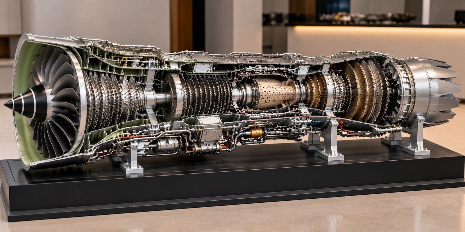
A physical model can help explain the general arrangement of an LNG terminal and identify its main equipment groups. In addition, specialized models can include selected cutaway components where the project requires a closer look at internal arrangements.
Corporate and Management Displays
Companies can use an LNG terminal model in meeting rooms, reception areas, and project presentation spaces. The model provides a tangible representation of the facility and supports discussions about the overall project scope.
LNG Terminal Physical Model vs. 3D Digital Model
A digital 3D model exists in computer software. Users can rotate it, change viewpoints, and review selected details on a screen.
In contrast, an LNG terminal physical model provides a tangible three-dimensional display. Viewers can walk around it, observe different elevations, and examine the relationship between the main equipment groups directly.
Both methods offer useful benefits. CAD files can support the fabrication of physical components, while the finished model can present the overall facility in an accessible format.
Therefore, project teams can combine digital design and physical model making when the project requires both detailed engineering information and a presentation-ready display.
Factors Affecting the Cost of LNG Terminal Scale Model Making
Model Size and Scale
The overall dimensions determine the amount of material, fabrication time, and structural support required. Larger models may also need additional transportation and installation planning.
Level of Detail
A model with detailed tanks, process equipment, pipe racks, miniature railings, platforms, and marine facilities requires more fabrication work than a simplified conceptual model.
Number of Components
The quantity of storage tanks, buildings, pipelines, process units, and supporting structures also affects the total work involved.
Materials and Fabrication Methods
Acrylic, engineering plastics, MDF, plywood, metal components, and 3D-printed parts each have different material and production requirements.
Lighting and Special Features
LED lighting, protective covers, detachable sections, and selected interactive elements can add to the project cost.
Availability of Drawings
Complete and coordinated CAD drawings can help the team plan fabrication more efficiently. Projects with limited references may require additional layout development and clarification.
For these reasons, the model-making company should prepare a project-specific quotation after reviewing the drawings, dimensions, scale, detail requirements, and delivery arrangements.
How to Choose an Industrial Model Making Company
Choosing the right industrial model making company can make a significant difference to the final presentation.
First, review the company’s previous work in industrial plant models, engineering models, piping models, and infrastructure displays. Look for consistent fabrication, realistic equipment details, clean finishes, and organized layouts.
Next, discuss the project drawings, required dimensions, material choices, lighting, and expected delivery schedule. Clear communication at the planning stage helps the model-making team understand the intended result.
Additionally, ask how the company will handle transportation, installation, and protection of delicate components. These considerations become particularly important for large exhibition models.
A professional model maker should focus on both appearance and accuracy. The model should communicate the approved project layout clearly rather than simply add decorative industrial equipment.
Why Choose PAL Design Models for LNG Terminal Scale Models?
PAL Design Models provides custom scale model making services for architectural, industrial, engineering, and infrastructure projects.
For LNG terminal projects, the team can plan a physical model around the principal storage tanks, processing areas, piping networks, marine facilities, LNG carrier, roads, and support buildings.
The fabrication approach can match the project’s purpose. For example, an exhibition model may emphasize the overall facility and presentation quality, while a technical model may require more detailed equipment arrangements and pipe racks.
Depending on the requirements, suitable methods may include manual model making, CAD-based component development, laser cutting, and 3D printing.
Furthermore, the team can plan the baseboard, surface finishes, and optional lighting according to the agreed display requirements.
To discuss a custom LNG Terminal Scale Model, prepare the available project drawings, CAD files, reference photographs, approximate dimensions, and preferred level of detail. These details help the model-making team understand the project and prepare a suitable proposal.
Visit the official website for more information about industrial and engineering model making services:
Frequently Asked Questions About LNG Terminal Scale Model Making
What is an LNG Terminal Scale Model?
An LNG Terminal Scale Model is a physical, three-dimensional representation of a liquefied natural gas facility. It can include storage tanks, pipelines, process equipment, marine facilities, buildings, and supporting infrastructure.
Which components can an LNG terminal model include?
The model can include LNG storage tanks, an LNG carrier, unloading arms, process equipment, pipe racks, pumps, control buildings, access roads, and harbor facilities. The final selection depends on the project layout.
Can you make an LNG terminal model using CAD drawings?
Yes. CAD drawings and 3D files help establish the model’s dimensions, equipment positions, and fabrication details. The final accuracy depends on the completeness and quality of the references.
Can the model include LED lighting?
Yes. The model maker can install LED lighting to highlight selected tanks, buildings, process areas, roads, and marine facilities according to the display requirements.
Which materials work well for LNG terminal models?
Suitable materials include acrylic, ABS, other engineering plastics, MDF, plywood, metal components, and 3D-printed parts. The team selects materials according to the component shape, scale, durability, and finishing requirements.
How do you select the model scale?
The model scale depends on the terminal’s overall dimensions, available display space, equipment quantity, and required level of detail. The project drawings help determine the most practical scale.
How much does an LNG terminal physical model cost?
The cost depends on the dimensions, scale, number of components, fabrication complexity, materials, lighting, and delivery requirements. A quotation requires a review of the project details.
Can you make import and export terminal models?
Yes. An import terminal model may focus on unloading and regasification, while an export terminal model may include gas treatment, liquefaction, storage, and loading facilities. The layout must follow the selected project’s requirements.
Is an LNG terminal model suitable for exhibitions?
Yes. A professionally fabricated model can support industrial exhibitions, energy trade shows, engineering presentations, project reviews, and corporate displays.
Can the model show the terminal and LNG carrier together?
Yes. The model maker can place the terminal, storage tanks, processing areas, jetty, harbor, and LNG carrier on a shared baseboard, provided the selected scale and display dimensions allow it.
Conclusion
An LNG Terminal Scale Model presents the main equipment, storage facilities, pipelines, and marine infrastructure of a liquefied natural gas terminal in a clear physical format.
By combining careful layout planning, suitable materials, detailed equipment fabrication, realistic piping, and professional finishing, model makers can create an informative representation of a complex industrial facility.
Moreover, the model can help project owners, EPC contractors, engineering consultants, and energy companies communicate the overall terminal arrangement during presentations, technical reviews, and exhibitions.
Whether the project involves an LNG import terminal, export terminal, regasification facility, or terminal expansion, the model should follow the available engineering references and meet the intended display requirements.
PAL Design Models offers custom industrial scale model making services for engineering presentations and infrastructure projects. Visit https://paldesignmodels.com to explore the company’s services and discuss your LNG terminal model requirements.