Industrial Prototype Model: The Essential Guide to Industrial Prototype Model Making
An Industrial Prototype Model is a physical representation of a machine, product, production system, industrial component, or complete industrial system created before final manufacturing or implementation. It helps engineers, designers, manufacturers, project teams, and clients understand how a proposed concept will look, fit, and function in a physical environment.
While an industrial prototype model is not simply a presentation model, it can focus on design verification, component arrangement, assembly, dimensions, movement, functionality, safety, and manufacturing requirements. Depending on the project, it can be a non-working presentation prototype, a functional prototype, or a working scale model with operating parts.
Industrial prototype models are widely applicable to manufacturing plants, machinery, production systems, automation equipment, material-handling systems, process plants, engineering equipment, industrial products, and custom mechanical assemblies. A well-developed prototype can turn a technical drawing or digital design into a physical object that project teams can inspect from different points of view. Physical prototypes are also commonly used to evaluate feasibility, form, function, and manufacturability before larger production commitments.
What Is an Industrial Prototype Model?
An Industrial Prototype Model is a physical model developed to represent an industrial product, machine, equipment arrangement, production process, or engineering concept. The prototype can be created at full size or at a selected scale according to the project’s purpose.
The prototype can represent a production machine with its major components, a conveyor with working belts, a factory production line, a processing unit, a robotic work cell, or a complete industrial plant layout.
The model can include structural frames, motors, tanks, pipes, conveyors, platforms, ladders, safety railings, control panels, electrical cabinets, storage areas, machinery, and other components. Designers can use these elements to communicate the relationship between different parts of the proposed system.
A physical prototype provides a different perspective from a CAD drawing. Engineers can inspect the model from different sides, check component placement, discuss assembly requirements, and demonstrate the concept to clients or management. In industrial model making, precision, material selection, fabrication, and detailing all contribute to the quality and usefulness of the finished physical model.
Why Industrial Prototype Models Are Important
Industrial projects can include hundreds of technical components, and understanding these components from drawings may sometimes be challenging for non-technical stakeholders. An industrial prototype model creates a physical reference that can make the concept easier to understand.
First, the model provides a clear visual representation of the proposed design. Engineers can see the relative position of machines, structures, platforms, conveyors, pipes, tanks, and other equipment.
Second, a prototype supports design discussions. Project teams can physically point to a particular component and discuss proposed changes.
Third, prototypes can help identify spatial issues at an early stage. For example, equipment may appear correctly positioned in a drawing but create an access problem when represented as a physical arrangement.
Furthermore, industrial prototype models can support presentations, exhibitions, project approvals, investor meetings, engineering reviews, training programs, and product demonstrations.
A prototype can also be developed specifically around the question that the project team needs to answer. For example, one prototype may focus on appearance and dimensions, while another may focus on movement, assembly, or functionality.
Industrial Prototype Model for Product Development
Product development is one of the major applications of prototype models. Before a new industrial product goes into production, designers may create a physical prototype to inspect its shape, dimensions, component arrangement, and usability.
Industrial Products Represented in a Prototype Model
A product prototype can represent:
- Industrial machinery
- Mechanical equipment
- Pumps
- Compressors
- Valves
- Control systems
- Material-handling equipment
- Automated machines
- Production equipment
- Special-purpose machines
- Industrial tools
- Equipment housings
The prototype can represent the external appearance as well as important internal components when a cutaway or sectional design is required.
For example, a machine prototype may include a transparent section that allows viewers to see gears, shafts, motors, belts, pumps, or other internal mechanisms. This approach makes the prototype useful for technical presentations and educational demonstrations.
A physical prototype can also support repeated design development. Once a component or arrangement is physically reviewed, the digital design can be modified and another version can be produced.
Types of Industrial Prototype Models
Different projects require different types of prototypes. Therefore, the model-making approach depends on the purpose, level of detail, scale, and required functionality.
1. Conceptual Industrial Prototype Model
A conceptual prototype focuses primarily on the overall design and appearance of an industrial product or system.
It may not include every small component. Instead, it communicates the main form, size, structure, and arrangement.
Conceptual models are useful in the early stages of product development when designers want to present an idea before final engineering details are completed.
This type of model can help a team review the general direction of a design without investing in the complete detailing required for a final prototype.
2. Detailed Industrial Prototype Model
A detailed prototype includes a larger number of components and technical features.
The model may contain:
- Structural frames
- Equipment
- Pipes
- Platforms
- Railings
- Stairs
- Control panels
- Electrical cabinets
- Motors
- Conveyors
- Storage areas
- Safety systems
Detailed prototypes are useful when engineers and clients need to understand the complete physical arrangement.
The level of detailing can be adjusted according to the intended use. A presentation model may emphasize visual accuracy, while an engineering prototype may require additional technical components and functional features.
3. Functional Industrial Prototype Model
A functional prototype goes beyond appearance and can demonstrate a particular operation or mechanism.
For example, a functional model may demonstrate:
- Conveyor movement
- Rotating machinery
- Pump operation
- Robotic arm movement
- Opening and closing mechanisms
- Material transfer
- Automated production
- Hydraulic movement
- Pneumatic movement
Motors, gears, LEDs, switches, sensors, and electronic controllers can be integrated when required.
Functional prototypes are particularly useful when a design cannot be fully evaluated from appearance alone. A working mechanism can provide direct visual evidence of how selected parts interact.
4. Working Industrial Prototype Model
A working prototype demonstrates selected functions of the actual industrial system.
The model does not necessarily need to reproduce every operation of a full-scale plant. Instead, the important working principle can be represented at a smaller scale.
For example, a working production-line prototype can show material entering a conveyor, moving between processing stations, and reaching a final collection area.
This approach allows a complex industrial process to be presented in a compact physical format.
5. Mechanical Prototype Model
A mechanical prototype focuses on the physical and mechanical components of a machine.
It can demonstrate the relationship between:
- Gears
- Shafts
- Bearings
- Motors
- Belts
- Pulleys
- Levers
- Cylinders
- Rotating components
- Structural supports
Mechanical prototypes are particularly useful for engineering presentations and design evaluations.
Major Components of an Industrial Prototype Model
The components used in an industrial prototype depend on the project. However, a detailed industrial model can contain several important elements.
Industrial Machinery
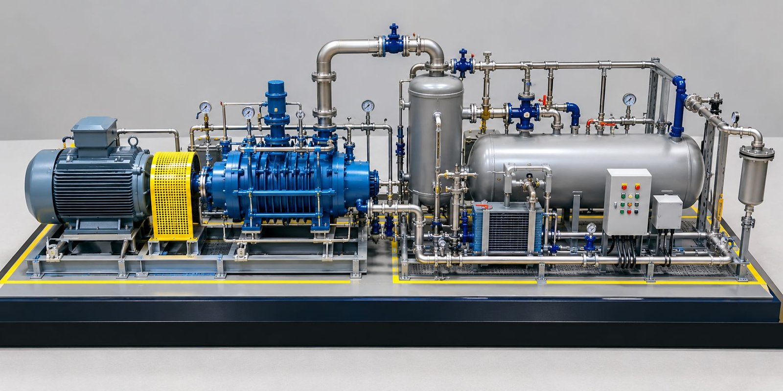
Machinery forms the central part of many industrial prototypes. Machines can be represented using different materials and manufacturing techniques to achieve accurate dimensions and realistic finishes.
The prototype can include pumps, compressors, mixers, processing equipment, generators, motors, production machines, and other industrial equipment.
Detailed machinery can include housings, control panels, access doors, motors, shafts, supports, and other visible components.
Conveyor Systems
Conveyors are important components in manufacturing and material-handling systems.
A prototype can show:
- Belt conveyors
- Roller conveyors
- Inclined conveyors
- Transfer conveyors
- Loading conveyors
- Automated material movement systems
A working conveyor model can include a miniature motor so that the belt moves during demonstration.
The conveyor can connect different production stations and visually explain the movement of materials through an industrial process.
Storage Tanks and Silos
Industrial facilities often require storage tanks, bins, hoppers, and silos. These structures can become important components of a scale prototype.
The model can represent cylindrical tanks, vertical silos, conical hoppers, access ladders, platforms, and safety railings.
These components can be arranged according to the actual plant layout so that viewers can understand their relationship with processing and material-handling systems.
Pipes and Process Lines
Piping is an essential part of many industrial systems. A detailed prototype can represent major process pipelines, utility lines, connecting pipes, valves, bends, supports, and equipment connections.
Different pipe colors can help distinguish between process lines and utility systems.
Pipe supports, bends, connections, and valves can also be reproduced at scale to increase the technical accuracy of the model.
Platforms and Walkways
Industrial machinery often requires access platforms and maintenance walkways.
A prototype can reproduce these elements using miniature structural members, stairs, handrails, ladders, and grating patterns.
These details improve the technical appearance of the model and help explain equipment accessibility.
Materials Used for Industrial Prototype Models
Material selection depends on the scale, complexity, required finish, and purpose of the prototype.
Common materials include:
- Acrylic
- PVC sheets
- ABS
- Foam board
- MDF
- Wood
- Metal
- Aluminum
- 3D-printed components
- Transparent sheets
- Acrylic rods
- Resin components
Different materials can be combined within a single model.
For example, acrylic can represent transparent protective covers, MDF can form the base, 3D printing can produce complex machinery, and metal or plastic rods can represent pipes and structural members.
The material should match the requirements of the individual component. Transparent materials can be useful for observation sections, while 3D-printed resin or plastic can reproduce complex shapes. Industrial scale models commonly combine digital fabrication and hand finishing to achieve both geometric accuracy and presentation quality.
3D Printing in Industrial Prototype Model Making
3D printing has become an important method for creating complex prototype components.
Traditional fabrication can require multiple cutting, shaping, drilling, and assembly processes. 3D printing can produce complex shapes directly from digital designs.
It is particularly useful for:
- Machine housings
- Mechanical parts
- Pipe fittings
- Special components
- Gear assemblies
- Equipment bodies
- Product prototypes
- Customized industrial components
The digital model can be adjusted before printing, allowing designers to develop different versions of a component.
3D printing also supports rapid prototyping because several design variations can be produced without creating completely new fabrication processes.
For complex industrial models, 3D printing can work together with other fabrication methods rather than replacing them completely. This combination allows individual components to be selected according to their geometry, required finish, and level of detail.
Laser Cutting for Industrial Prototypes
Laser cutting provides accurate cutting for materials such as acrylic, MDF, plywood, and selected plastics.
It can be used to create:
- Structural panels
- Machine frames
- Building components
- Platforms
- Equipment bases
- Industrial sheds
- Control panels
- Small architectural elements
Laser-cut parts can then be assembled to create a precise physical prototype.
This method is particularly useful when the model contains repeated panels, flat structural elements, accurately shaped bases, or components that require consistent dimensions.
Working Features in an Industrial Prototype Model
A working industrial prototype can include several functional features depending on the project’s requirements.
LED Lighting in Industrial Prototype Models
LED lighting can represent:
- Machine indicators
- Factory lighting
- Warning lights
- Control panels
- Equipment status
- Road lighting
- Emergency systems
Small LEDs can create a realistic presentation and also help viewers identify specific areas of the model.
Lighting can be installed inside buildings, around equipment, along roads, or within selected control areas.
Moving Conveyors
A miniature conveyor can operate using a small motor. This allows the model to demonstrate material movement.
The system can include a belt, rollers, motor, support frame, and control switch.
When activated, the conveyor can demonstrate the movement of material from one production area to another.
Rotating Machinery
Selected machinery components can rotate during a demonstration.
Small motors can drive fans, shafts, wheels, turbines, mixers, or other moving parts.
This feature can make the prototype more interactive while demonstrating the operating principle of a selected machine.
Robotic Movement
Industrial automation prototypes can include miniature robotic arms.
A robotic prototype may demonstrate:
- Picking a component
- Moving the component
- Rotating the arm
- Placing the component
- Returning to the original position
Such models can help explain automated production concepts in a simple physical format.
Industrial Factory Prototype Model
A factory prototype represents the complete industrial environment rather than one machine.
A detailed factory model can include:
- Production buildings
- Manufacturing lines
- Warehouses
- Loading areas
- Offices
- Utility buildings
- Storage tanks
- Internal roads
- Parking
- Security gates
- Landscaping
- Material-handling systems
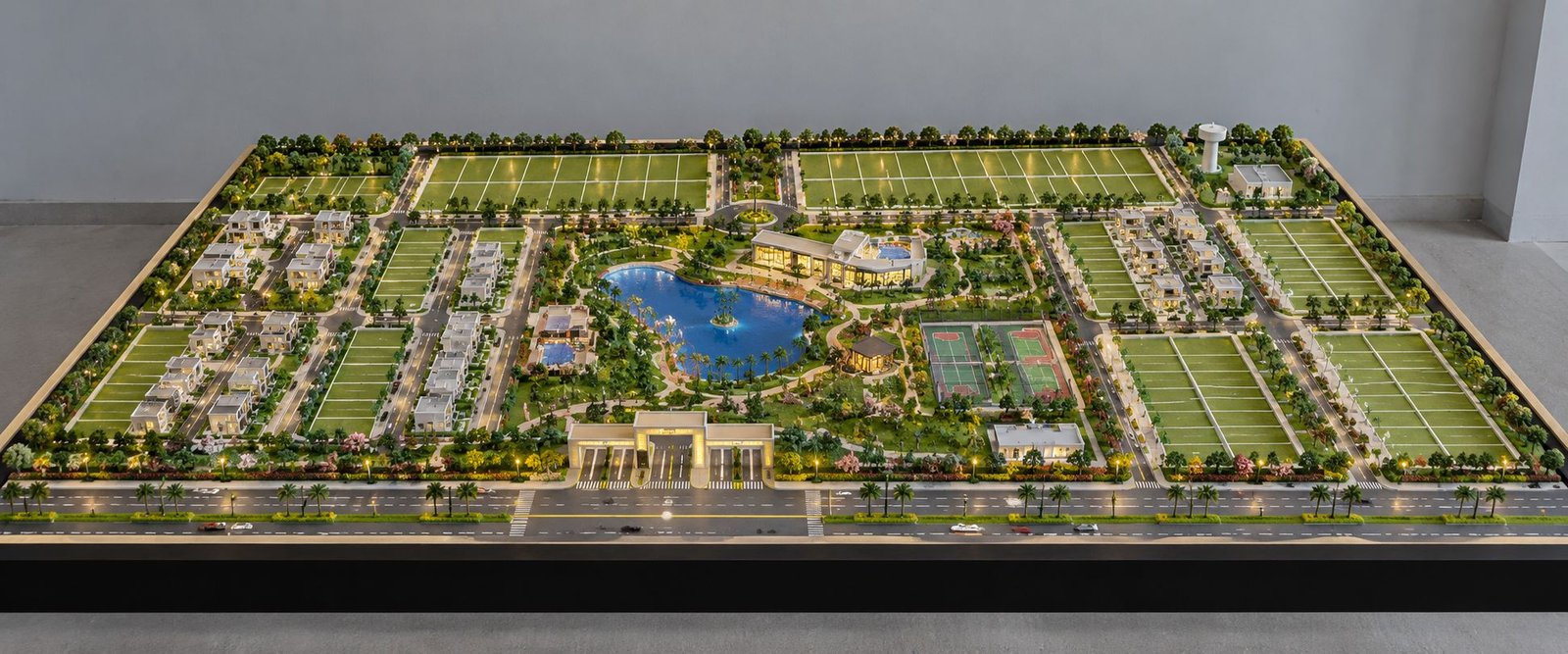
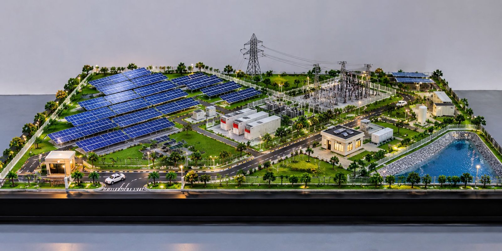
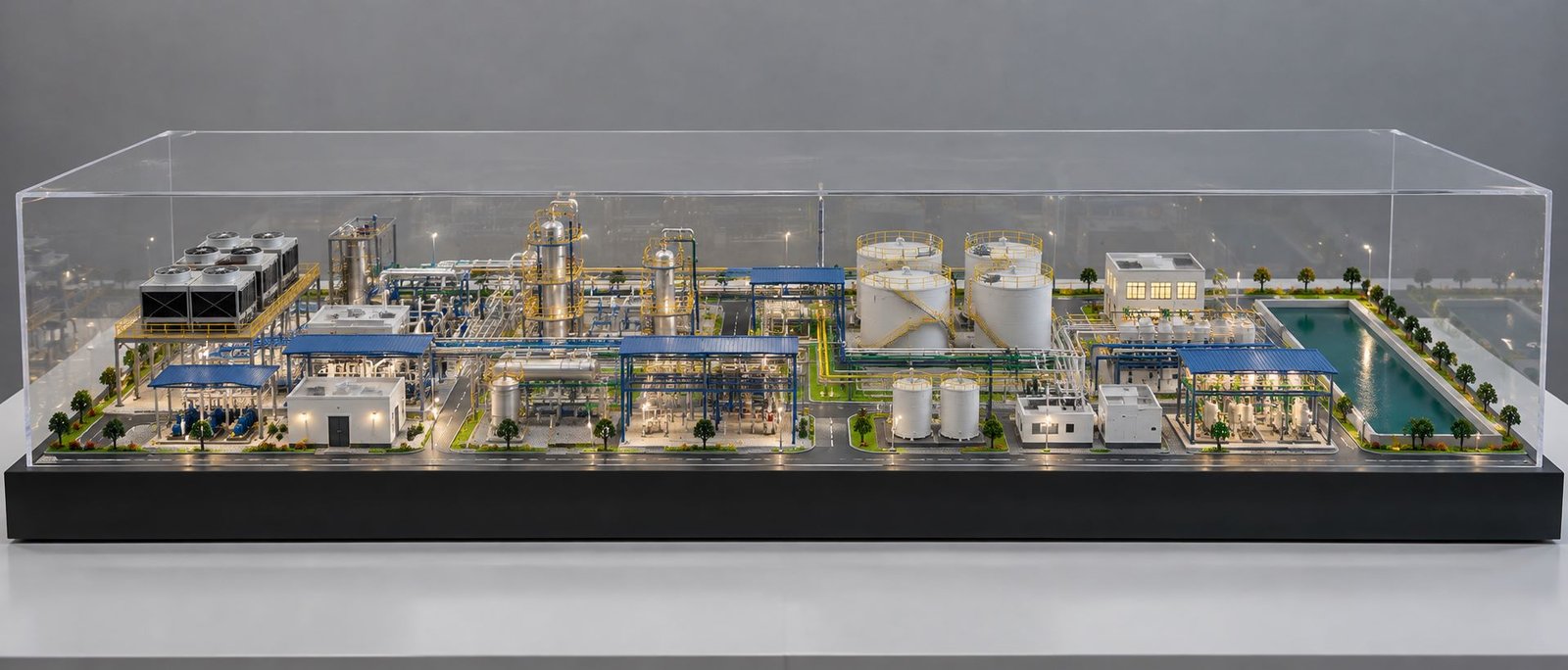
Factory prototypes are useful for planning and presentations because they can show how different departments and facilities are connected within the overall site.
A physical factory model can also make the relationship between production areas, warehouses, transportation routes, loading zones, and utility areas easier to understand.
Industrial Plant Prototype Model
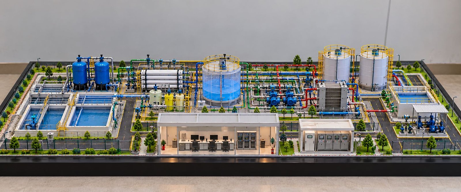
An industrial plant prototype can represent a larger process facility.
Depending on the project, it can include:
- Processing units
- Storage tanks
- Pipe racks
- Control rooms
- Utility areas
- Pumps
- Compressors
- Platforms
- Cooling systems
- Electrical equipment
- Maintenance areas
The model can use different levels of detail depending on whether it is intended for engineering review or presentation purposes.
A well-developed plant prototype can bring together equipment, buildings, pipework, access systems, storage areas, and utilities within one physical representation. Industrial scale models can represent large facilities such as manufacturing plants, refineries, processing units, warehouses, logistics facilities, and other industrial developments.
Industrial Automation Prototype Model
Automation is another important application for industrial prototype models.
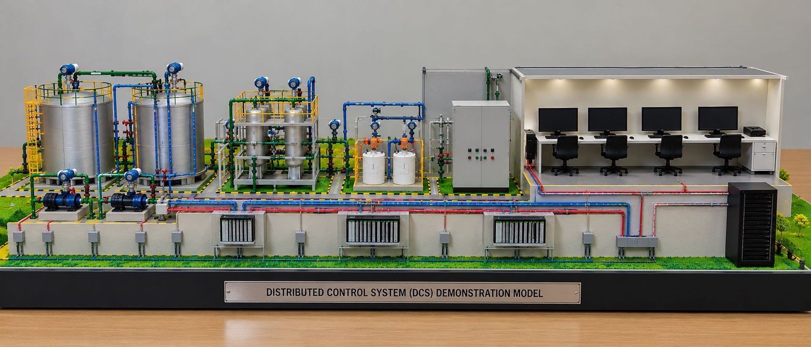
An automation prototype can demonstrate how machines communicate and work together within a production environment.
A model may include robotic arms, conveyors, sensors, assembly stations, inspection areas, control panels, and automated storage systems.
The physical model can demonstrate the movement of products through different stages.
For example, a component can enter the system, move along a conveyor, reach a robotic station, undergo a simulated assembly process, and then move toward packaging or storage.
This type of prototype can make an automated production concept easier to understand because the complete sequence appears within a single physical model.
Engineering Prototype Model vs Industrial Prototype Model
An engineering prototype generally focuses on engineering principles, mechanisms, components, and technical performance.
An industrial prototype can focus on a broader industrial product, machine, facility, or production system.
However, the two categories can overlap. A factory automation prototype can be both an industrial prototype and an engineering prototype.
Similarly, a mechanical machine prototype can be an industrial product prototype and a mechanical engineering prototype.
The exact classification depends on the project’s purpose.
The important factor is the objective of the prototype. If the primary goal is to evaluate a mechanism, the model may emphasize functional engineering. If the goal is to communicate a complete industrial system, the prototype may include a broader combination of equipment, buildings, infrastructure, and processes.
Scale Selection for Industrial Prototype Models
Scale selection is an important part of prototype planning.
A large industrial system may require a smaller scale so that the complete facility can fit on a manageable baseboard. A small mechanical product may require a larger scale to display its technical components clearly.
The selected scale should provide enough space for important details while keeping the model practical for transportation, handling, and presentation.
A proper scale also maintains consistent proportions between different components.
Scale should therefore be selected according to the size of the original system, available display space, required level of detail, and purpose of the model.
Baseboard and Presentation Design
The baseboard provides the foundation for the prototype and affects the overall presentation.
A professional industrial prototype usually benefits from a clean rectangular base with properly finished edges.
The baseboard can include:
- Industrial flooring
- Roads
- Equipment zones
- Landscaping
- Safety markings
- Parking
- Loading areas
- Labels
- Lighting
The model should remain visually balanced so that the machinery and technical components remain the main focus.
A properly designed baseboard also provides structural support and creates a clear boundary around the industrial environment.
Detailing in Industrial Prototype Models
Detailing separates a basic model from a professional industrial prototype.
Small elements can make the physical model easier to understand and closer to an actual industrial environment.
Useful details include:
- Handrails
- Ladders
- Pipe supports
- Cable trays
- Valves
- Safety barriers
- Warning signs
- Electrical panels
- Machine controls
- Structural columns
- Access platforms
- Service roads
- Drainage channels
- Lighting poles
However, detailing should remain relevant to the purpose of the model. Adding unnecessary elements can make the prototype visually crowded.
The best detailing approach maintains a balance between technical accuracy and clear presentation.
Industrial Prototype Model for Client Presentation
A physical prototype can provide a strong visual aid during client presentations.
Instead of explaining a complex industrial system entirely through drawings, project teams can use the physical model to demonstrate the concept.
Clients can observe equipment locations, building relationships, access routes, production zones, and overall project organization.
A well-presented prototype can also support discussions about proposed modifications.
The physical model can therefore become a common visual reference for designers, engineers, project managers, clients, and other stakeholders.
Industrial Prototype Models for Exhibitions
Industrial companies can use prototype models at exhibitions, trade shows, technical events, and corporate displays.
A detailed physical model can attract attention because visitors can observe the equipment and production system from different angles.
For exhibition use, the prototype can include integrated lighting, transparent covers, moving components, and identification labels.
A protective acrylic enclosure can also help protect delicate components during transportation and public display.
An exhibition-focused prototype can combine technical accuracy with presentation features so that visitors can understand the product or industrial system quickly.
Educational and Training Applications
Industrial prototype models can also support technical education and training.
Students and trainees can understand industrial processes more easily when they can physically observe equipment relationships.
For example, a process plant prototype can demonstrate the movement of material between storage, processing, transfer, and output stages.
Similarly, a mechanical prototype can help explain gears, shafts, motors, pumps, and other mechanisms.
Working prototypes can provide an interactive learning experience because users can observe movement rather than only reading about the process.
This makes physical prototypes useful for engineering institutions, technical demonstrations, workshops, and industrial training environments.
Industrial Prototype Model Development Process
Professional prototype development normally follows a structured process.
Step 1: Understanding the Project
The first stage involves understanding the purpose of the prototype.
The model maker reviews drawings, CAD files, dimensions, reference images, equipment layouts, and project requirements.
The team also identifies whether the model needs to be visual, functional, working, or suitable for a specific presentation or exhibition.
Step 2: Scale and Layout Planning
The required scale and overall model size are established.
The team determines how much space the machinery, structures, roads, platforms, and other elements will occupy.
This stage helps establish the overall proportions before fabrication begins.
Step 3: Digital Preparation
CAD drawings or 3D files can be prepared for fabrication.
Complex components may be separated into smaller parts for 3D printing, laser cutting, or manual fabrication.
Digital preparation also helps organize components and maintain consistent dimensions.
Step 4: Baseboard Fabrication
The baseboard is prepared according to the planned dimensions.
Roads, flooring, equipment zones, and other basic site elements can be added at this stage.
Step 5: Component Manufacturing
Individual machinery, tanks, structures, pipes, conveyors, platforms, and other components are fabricated.
Different manufacturing methods can be combined depending on the component.
Step 6: Assembly
The components are assembled according to the approved layout.
Proper alignment is important because even a small positional error can affect the overall appearance and technical representation.
Step 7: Electrical and Working Features
If the prototype includes LEDs, motors, switches, sensors, or moving components, these systems are installed during the appropriate assembly stages.
The working system should remain accessible for testing and maintenance where necessary.
Step 8: Finishing and Detailing
The model receives final painting, surface finishing, labels, safety markings, railings, landscaping, and other details.
These finishing elements create a consistent and professional appearance.
Step 9: Quality Inspection
The completed prototype is checked for structural stability, component alignment, finish quality, electrical operation, and overall presentation.
The inspection helps ensure that the finished model meets the requirements established at the beginning of the project.
Benefits of Physical Industrial Prototype Models
Physical industrial prototypes offer several practical benefits.
They provide a clear three-dimensional representation of complex systems. They also make technical discussions easier because project teams can directly observe and discuss physical components.
Prototypes can help identify spatial relationships between equipment, structures, and access areas.
Working prototypes can also demonstrate selected mechanical or electrical principles.
Furthermore, physical models can support client presentations, exhibitions, training, product development, design reviews, and project communication.
A physical prototype can also help teams identify design questions earlier, allowing selected elements to be reviewed before larger manufacturing or implementation decisions. Prototype development is commonly used to reduce uncertainty around form, function, feasibility, and manufacturability.
Future of Industrial Prototype Model Making
Industrial prototype development continues to evolve as digital design and fabrication technologies become more accessible.
3D printing, CNC machining, laser cutting, digital modeling, and electronic control systems can be combined to produce increasingly detailed prototypes.
Future industrial models can combine physical components with lighting, sensors, moving mechanisms, and interactive controls.
Digital design also allows prototype components to be modified quickly before fabrication.
As industrial systems become more automated and technically complex, physical prototypes can continue to provide a useful bridge between digital engineering concepts and physical understanding.
The growing combination of digital fabrication and physical model making can also make it easier to create complex components, detailed assemblies, and functional demonstrations within a single prototype.
Conclusion
An Industrial Prototype Model provides a practical way to transform an industrial concept into a physical representation. From a single machine to a complete factory or process plant, prototype models can represent equipment, structures, production systems, automation, material handling, and industrial environments in a clear three-dimensional format.
Depending on project requirements, the prototype can remain purely visual or include working features such as conveyors, rotating machinery, robotic arms, LED lighting, switches, and other mechanisms.
The combination of 3D printing, laser cutting, CAD-based fabrication, manual detailing, electrical integration, and precision assembly allows industrial prototype models to achieve a high level of detail.
A properly planned industrial prototype can therefore support product development, engineering communication, factory planning, technical presentations, exhibitions, training, and design evaluation. It provides a physical platform where complex industrial concepts become easier to see, discuss, demonstrate, and understand.