Hydraulic Engineering Models for Technical Presentations
Hydraulic engineering systems play an important role in industrial machines, lifting equipment, construction machinery, production facilities, and mechanical systems. However, complex hydraulic arrangements can become difficult to understand through technical drawings and schematic documentation alone. Therefore, engineers and clients often need a clear three-dimensional view of equipment configuration, piping connections, hydraulic machinery, control mechanisms, and component relationships.
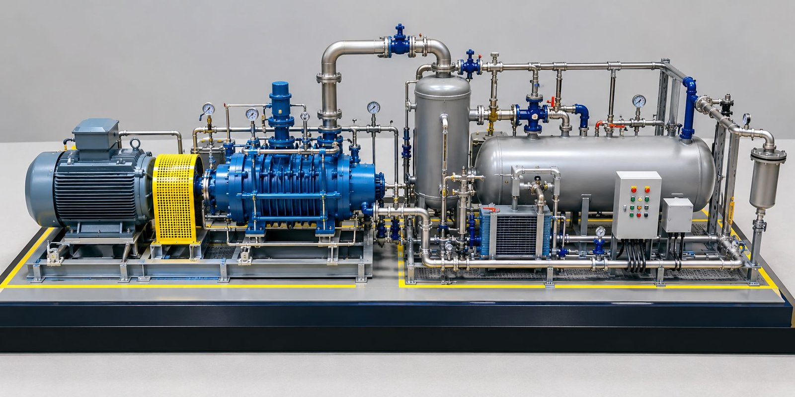
A Hydraulic Engineering Model provides this physical perspective. Instead of studying the system only through drawings, viewers can examine a detailed miniature representation of the complete equipment arrangement. Moreover, the model can show pumps, motors, reservoirs, cylinders, actuators, valves, gauges, hoses, pipes, manifolds, control panels, platforms, supports, and other components in one organized presentation.
Furthermore, a professionally fabricated scale model helps explain how these components connect and interact within a specific equipment area. As a result, hydraulic engineering models can support technical presentations for engineers, equipment manufacturers, industrial consultants, EPC organizations, engineering institutions, project managers, and clients.
What Is a Hydraulic Engineering Model?
A hydraulic engineering model is a scaled physical representation of a hydraulic system, hydraulic machine, equipment configuration, or industrial hydraulic installation.
Depending on the project requirements, model makers can develop the model around a complete hydraulic system or a specific application. For example, the model can include a hydraulic power unit, pumps, motors, reservoirs, pressure-control components, valves, actuators, piping, flexible hoses, gauges, control equipment, and supporting structures.
Understanding Component Relationships
A detailed hydraulic engineering model does more than reproduce the appearance of a machine. Instead, it explains the relationship between different components.
For instance, the model can show a hydraulic reservoir connected to a pump. Then, the pump can connect to a manifold through miniature pipes or hoses. From the manifold, additional connections can reach valves and actuators. At the same time, miniature pressure gauges can appear at important points, while a control cabinet can represent the monitoring and control side of the system.
As a result, viewers can understand the complete hydraulic arrangement through one physical model.
Purpose of Hydraulic Models for Technical Presentations
The primary purpose of a hydraulic engineering model is to communicate technical information in a clear and visual format.
Engineering drawings contain extensive information. However, viewers need technical knowledge to interpret complex layouts and schematic drawings correctly. In contrast, a physical model provides a direct three-dimensional representation of the equipment.
Technical Information Presented Through the Model
A detailed model can demonstrate:
- Equipment configuration
- Hydraulic component arrangement
- Piping connections
- Hose routing
- Pump and motor arrangement
- Reservoir location
- Valve configuration
- Cylinder arrangement
- Control equipment
- Pressure monitoring locations
- Access and maintenance areas
- Structural supports
- Overall equipment layout
Furthermore, the presenter can point directly to individual components during a technical discussion. Therefore, the model can support engineering meetings, client presentations, exhibitions, training sessions, project reviews, authority meetings, and other professional activities.
Detailed Physical Model Design
A professional hydraulic model should look like a carefully fabricated miniature industrial installation rather than a simple conceptual display. Therefore, model makers need to balance technical accuracy, component detailing, scale, materials, finishing, and overall presentation.
A rectangular baseboard provides a clean foundation for the equipment. In addition, the base can separate different equipment zones and provide sufficient space for piping, supports, walkways, and machinery.
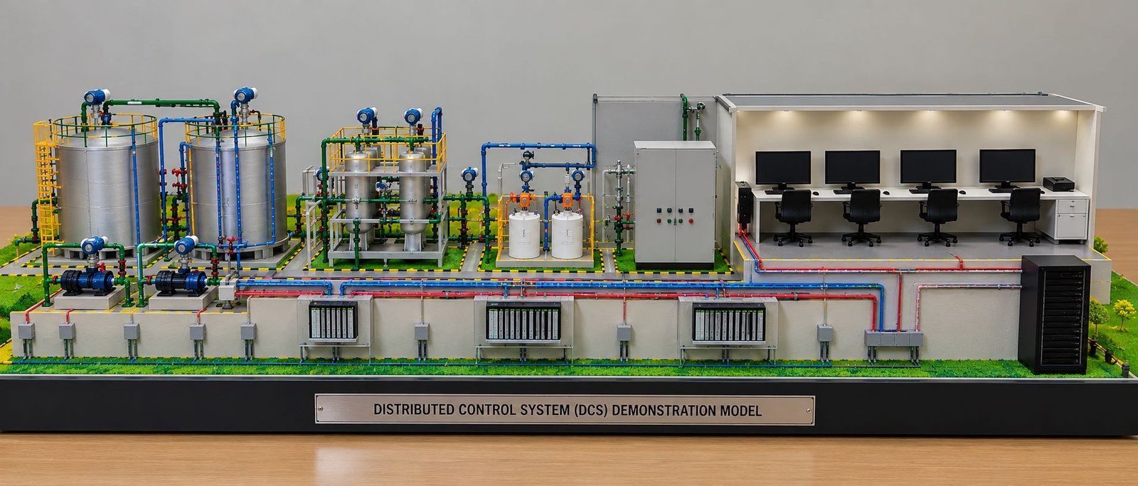
Wide and Low-Height Model Configuration
A wide and low-height hydraulic model provides an effective presentation format for technical displays.
The wider configuration creates more horizontal space for pumps, reservoirs, piping, cylinders, platforms, control panels, and other equipment. Meanwhile, the low overall height allows viewers to see smaller components without larger machines blocking them.
Moreover, this arrangement works well for exhibition displays, technical presentations, client meetings, training centers, and industrial model showcases.
Hydraulic Reservoir or Oil Tank
The hydraulic reservoir forms an important part of a hydraulic system. Therefore, the physical model should represent the tank with sufficient detail.
Depending on the actual equipment, model makers can create the reservoir as a rectangular or cylindrical tank. In addition, the model can reproduce important external fittings and connections to make the miniature tank more realistic.
Hydraulic Reservoir Details
The model can include:
- Tank body
- Filler arrangement
- Level indicator
- Breather
- Inspection cover
- Hydraulic connections
- Drain connection
- Return piping
- Support structure
Model makers can fabricate the tank using acrylic, metal, PVC, resin, or other suitable materials. Furthermore, a transparent or translucent section can help viewers understand the internal arrangement when the project requires an educational or demonstration model.
Hydraulic Pump and Motor Assembly
The hydraulic pump plays a critical role in the system because it transfers mechanical energy into hydraulic energy. Therefore, the pump and motor assembly deserves careful attention in a physical model.
A miniature electric motor can drive the hydraulic pump through a small coupling arrangement. Moreover, the model can show the pump housing, mounting base, suction connection, discharge connection, hoses, fittings, and bolted details.
Pump and Motor Components
A detailed pump and motor assembly can include:
- Electric motor
- Pump housing
- Coupling
- Mounting base
- Suction connection
- Discharge connection
- Hydraulic hoses
- Pipe fittings
- Bolted connections
Additionally, different materials and colors can distinguish the motor, pump, piping, and mounting structure.
Hydraulic Power Unit
A hydraulic power unit combines several important components into one equipment assembly.
For example, the model can show the reservoir, electric motor, hydraulic pump, valves, filters, manifold, pressure gauges, hoses, and control equipment on a compact skid or structural frame.
Hydraulic Power Unit Components
The miniature power unit can include:
- Pumps
- Motors
- Oil tank
- Filters
- Valves
- Pressure gauges
- Manifolds
- Hoses
- Pipe fittings
- Control components
- Electrical cabinet
Consequently, the complete assembly provides a clear physical representation of the hydraulic power supply system. Moreover, viewers can understand how several components work together within a compact equipment arrangement.
Hydraulic Piping and Hoses
Hydraulic piping forms one of the most important visual elements of a hydraulic engineering model.
Model makers can use rigid miniature pipes for permanent connections and flexible black hoses for flexible hydraulic connections. Furthermore, they can route these lines according to the actual equipment arrangement.
Hydraulic Connections
The model can demonstrate connections between:
- Reservoir and pump
- Pump and manifold
- Manifold and control valves
- Valves and cylinders
- Return lines
- Auxiliary equipment
In addition, miniature elbows, tees, couplings, connectors, clamps, and fittings can improve the overall realism of the piping system.
As a result, the piping network becomes easier to understand during technical presentations.
Hydraulic Valves
Hydraulic valves control fluid movement within the system. Therefore, their position and connection arrangement deserve clear representation in the model.
Types of Hydraulic Valves
Depending on the project, the model can include:
- Directional valves
- Pressure-control valves
- Flow-control valves
- Isolation valves
- Other specialized valve assemblies
Moreover, model makers can keep important valves accessible and clearly visible so viewers can understand their relationship with the surrounding piping.
Hydraulic Manifold
A hydraulic manifold connects multiple valves, actuators, gauges, and hydraulic lines within a compact assembly.
The physical model can position the manifold between the pump and the downstream control components. Meanwhile, miniature pipes and hoses can connect the manifold from different directions.
As a result, the manifold becomes an important focal point because it demonstrates how multiple hydraulic circuits connect within one system.
Pressure Gauges and Instrumentation
Pressure gauges add technical detail while also helping viewers understand monitoring points within a hydraulic circuit.
Model makers can place miniature gauges near pumps, manifolds, valves, or other important locations. In particular, these small components can make the model look more technically complete.
Instrumentation Details
The model can also include:
- Pressure indicators
- Temperature indicators
- Level indicators
- Flow-related instruments
- Control switches
- Indicator lights
- Instrument connections
Therefore, the model presents more than mechanical equipment. In addition, it communicates the monitoring and control elements that support the hydraulic system.
Hydraulic Cylinders
Hydraulic cylinders convert hydraulic pressure into linear movement. Consequently, they form an important part of many hydraulic equipment models.
The model can position cylinders vertically or horizontally according to the actual machine configuration. Similarly, the model can show the cylinder connection with surrounding structures and hydraulic hoses.
Hydraulic Cylinder Details
A detailed miniature cylinder can include:
- Cylinder barrel
- Piston rod
- Mounting brackets
- Hydraulic ports
- Support structure
- Connecting hoses
Furthermore, a cutaway cylinder can reveal internal components and provide a better understanding of the piston arrangement.
Hydraulic Press Model
A hydraulic press provides an excellent example of how a physical model can explain the relationship between hydraulic power and mechanical movement.
The model can position a vertical hydraulic cylinder above a working platform and connect it to the hydraulic power unit through miniature hoses and valves.
Hydraulic Press Components
A detailed hydraulic press model can include:
- Main frame
- Hydraulic cylinder
- Pump
- Motor
- Reservoir
- Hydraulic hoses
- Control valves
- Pressure gauge
- Control cabinet
- Work table
- Safety structure
Thus, the model clearly demonstrates the relationship between the hydraulic power unit and the working mechanism.
Safety Features
In addition, the model can include safety structures, railings, markings, guards, and controlled access areas to create a realistic industrial presentation.
For this reason, safety details can contribute to both technical communication and visual realism.
Hydraulic Actuator Model
A hydraulic actuator uses hydraulic pressure to create mechanical movement.
A physical model can show a horizontal actuator mounted on a structural frame. In this way, the arrangement can demonstrate the actuator’s stroke principle within a mechanical system.
Hydraulic Actuator Details
The model can include:
- Cylinder body
- Piston rod
- Mounting brackets
- Hydraulic connections
- Support structure
Furthermore, the actuator can connect directly to miniature hydraulic piping to demonstrate its relationship with the rest of the system.
Hydraulic Control Panel
A hydraulic system also requires control equipment for operation and monitoring.
A miniature control panel can add significant technical detail to the physical model. Moreover, it can visually connect the mechanical equipment with the control side of the system.
Control Panel Components
The model can include:
- Display
- Push-button controls
- Indicator lights
- Selector switches
- Emergency-stop switch
- Control cabinet
Although the miniature panel does not need to operate as a real control system, it can provide a realistic representation of the equipment’s control section.
Structural Platforms and Support Frames
Hydraulic power units and industrial hydraulic systems require suitable structural support. Therefore, the physical model can include miniature steel frames, equipment mounts, platforms, stairs, handrails, and support brackets.
Industrial Structural Details
Model makers can fabricate these elements using miniature metal profiles, acrylic, PVC, or other suitable materials.
Furthermore, yellow safety railings can visually distinguish access areas and reinforce the industrial appearance of the model.
Walkways and Access Areas
Access areas help explain how operators and maintenance teams can approach different equipment sections.
A physical model can include miniature walkways around the main hydraulic equipment. Similarly, stairs and platforms can connect elevated equipment areas.
As a result, viewers can understand not only the equipment arrangement but also the relationship between machinery and access space.
Equipment Base and Skid
A skid or equipment base provides structural support for a hydraulic power unit.
The physical model can represent the skid as a rectangular frame with mounting points for pumps, motors, tanks, manifolds, and other components.
Skid Details
The skid can also include:
- Equipment mounts
- Pipe supports
- Access areas
- Safety markings
- Structural members
- Mounting plates
In addition, this arrangement gives the hydraulic model a professional industrial appearance.
Miniature Piping Details
Small details can significantly improve the realism of a hydraulic engineering model.
Hydraulic Piping Components
The model can include:
- Elbows
- Tees
- Couplings
- Flanges
- Unions
- Pipe clamps
- Hose connections
- Valve handles
- Pressure gauges
- Supports
- Brackets
Moreover, accurate placement of these small components helps viewers understand the connection scheme more clearly.
Color Coding in Hydraulic Models
Color coding can improve both presentation quality and system identification.
For example, model makers can use different colors for hydraulic equipment, structural elements, safety railings, control panels, and different hydraulic circuits.
Visual Identification
The exact color scheme can follow the project requirements. In addition, consistent color usage can help viewers distinguish between different systems during a technical presentation.
Therefore, color becomes both a visual and technical communication element.
Cutaway Hydraulic Models
Cutaway models provide an effective way to demonstrate internal components.
For example, a hydraulic cylinder can use a transparent section to show the piston, cylinder barrel, and internal arrangement.
Internal Component Visualization
Similarly, model makers can create partial cutaway sections for pumps, valves, and other components.
Consequently, viewers can understand internal mechanisms while still seeing the external equipment arrangement.
3D Printing for Hydraulic Models
3D printing can produce complex miniature components with consistent dimensions and detailed shapes.
3D-Printed Components
Model makers can use 3D printing for:
- Pump housings
- Valve bodies
- Motor components
- Cylinder parts
- Flanges
- Special fittings
- Equipment brackets
- Control components
- Custom machinery parts
Furthermore, 3D printing can help reproduce multiple identical components efficiently.
Laser Cutting for Structural Components
Laser cutting provides another useful fabrication technique for hydraulic engineering models.
Laser-Cut Components
Model makers can use laser cutting for:
- Equipment bases
- Platforms
- Panels
- Structural frames
- Stairs
- Railings
- Machine plates
- Control cabinets
As a result, the model can combine precise structural components with detailed 3D-printed mechanical parts.
Hand Assembly and Finishing
Modern fabrication technologies cannot replace careful manual assembly.
Model makers need to position miniature components accurately, connect piping, route hoses, align equipment, and complete the final finishing. Meanwhile, each component needs to maintain the correct scale and position.
Final Model Finishing
The final process can include:
- Component alignment
- Manual assembly
- Piping connections
- Surface finishing
- Painting
- Detail correction
- Base finishing
- Final inspection
Therefore, manual craftsmanship remains important for achieving a professional physical model.
Hydraulic Models for Technical Training
Physical hydraulic models can support technical training by providing a clear three-dimensional representation of system components.
A training model can include labels, transparent sections, cutaway components, and visible connections. In addition, the model can use different colors to make major systems easier to identify.
Training Applications
The model can help explain the relationship between:
- Pumps
- Valves
- Cylinders
- Reservoirs
- Pressure gauges
- Hydraulic connections
Consequently, students, technicians, and engineering teams can use the physical model as a visual reference during training sessions.
Hydraulic Models for Client Presentations
Physical hydraulic models can also support client presentations.
A detailed model allows the technical team to explain equipment configuration directly on the physical display. Instead of relying entirely on drawings, the presenter can point to the pump, reservoir, manifold, cylinder, control panel, or piping connection.
Moreover, the client can examine the complete equipment arrangement from different viewing angles.
As a result, the model can make technical discussions more visual and easier to follow.
Hydraulic Models for Industrial Projects
Industrial companies can use physical hydraulic models to present machinery, production systems, equipment layouts, and specialized hydraulic installations.
A model can represent an individual machine or a complete equipment area containing multiple hydraulic systems.
Large Industrial Hydraulic Models
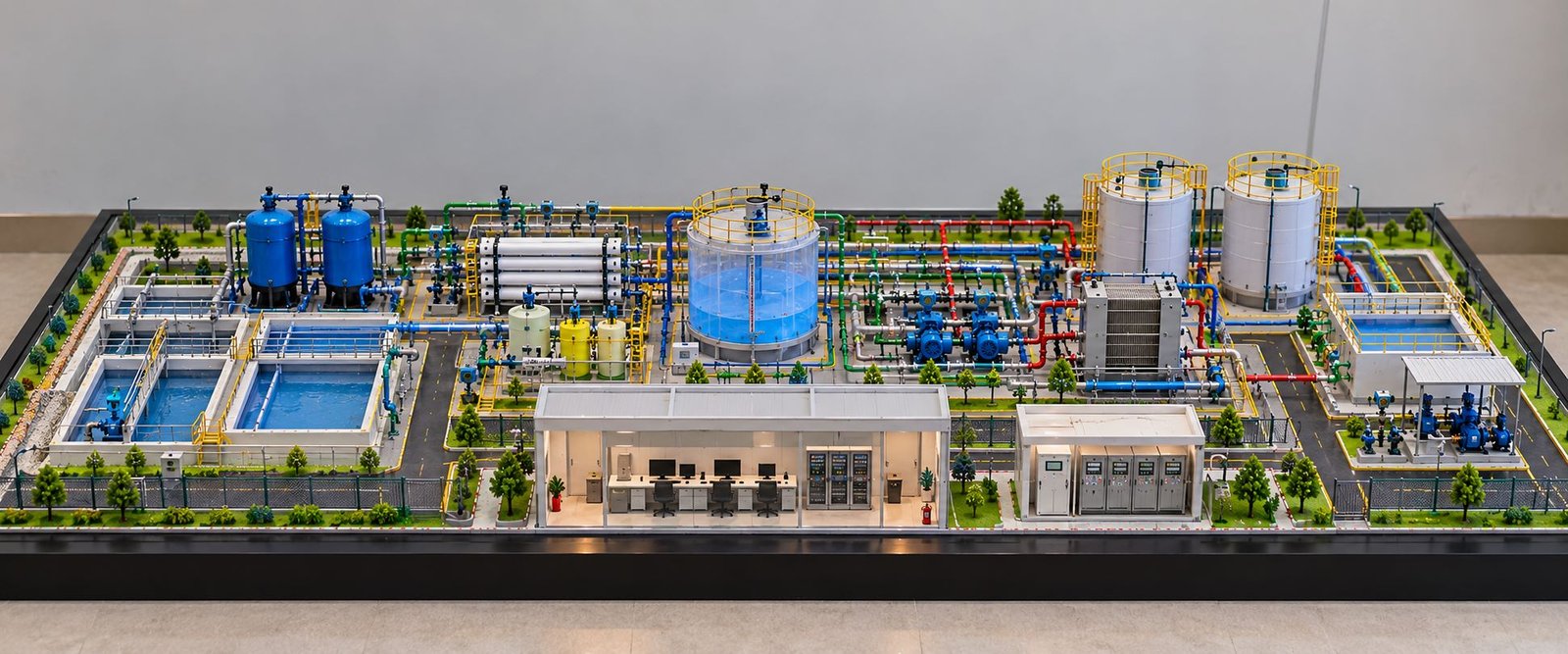
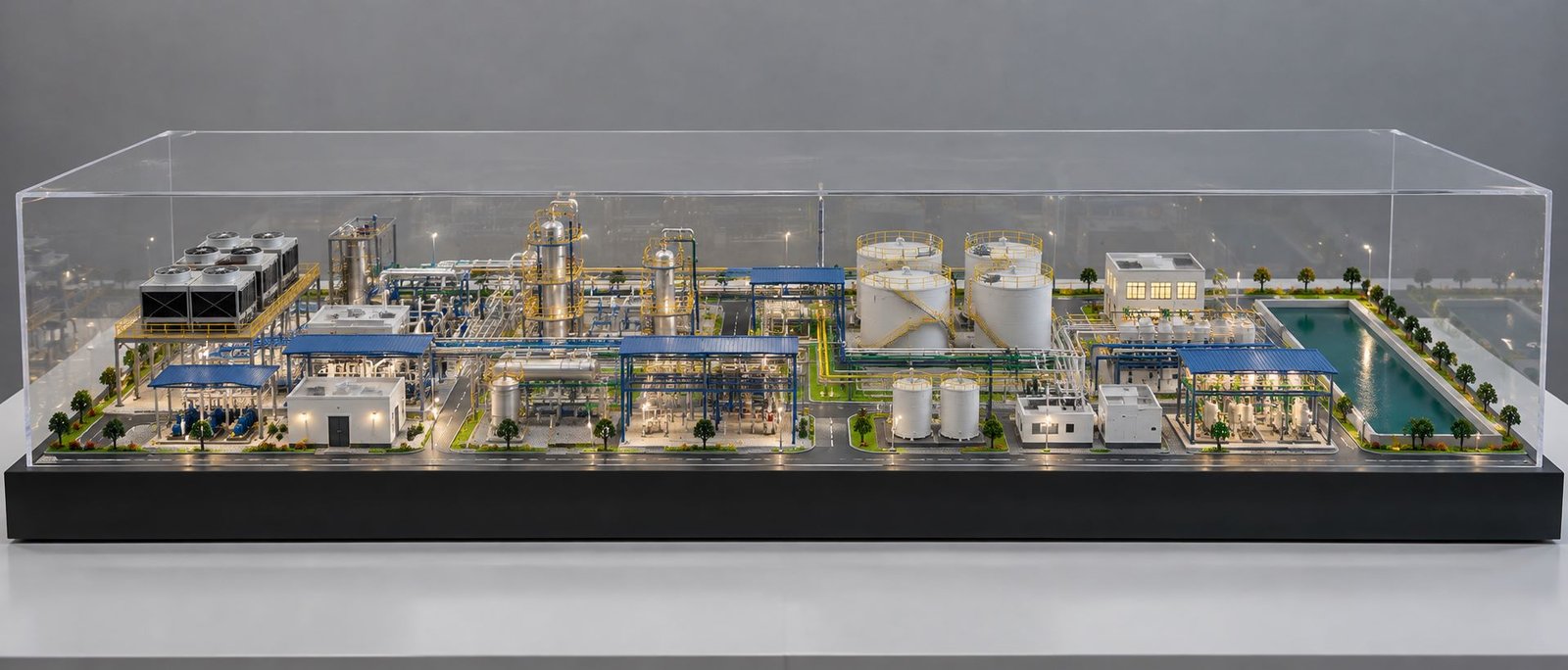
For larger projects, model makers can arrange multiple hydraulic systems on one wide baseboard.
In this way, viewers can see the complete equipment layout from the perimeter while still maintaining sufficient component detail.
Presentation Base and Display Design
The presentation base contributes significantly to the overall appearance of the model.
A rectangular base can provide a clean and organized foundation for the equipment. Furthermore, the base can separate individual equipment zones and improve the overall presentation.
Industrial Base Design
The base can include:
- Equipment zones
- Safety markings
- Access areas
- Mounting zones
- Walkways
- Small lighting fixtures
A black perimeter frame can create strong visual contrast against the equipment and help the miniature industrial components stand out.
Display Lighting
Small LED lights can highlight selected model areas. However, the lighting should remain controlled so that it supports the presentation without hiding important technical details.
Importance of Scale
Selecting the correct scale is essential for a detailed hydraulic engineering model.
Small-Scale Challenges
If the scale becomes too small, components such as valves, pressure gauges, fittings, and miniature piping may become extremely difficult to fabricate and assemble.
Large-Scale Challenges
On the other hand, an unnecessarily large scale can increase the overall model size, material requirements, fabrication time, and display space.
Selecting the Correct Scale
Therefore, model makers should consider the available display dimensions, equipment size, required detailing, viewing distance, and presentation purpose before selecting the final scale.
For this reason, scale selection should take place during the early planning stage of the model.
Accuracy and Proportion
Accurate proportions help create a realistic and technically convincing physical model.
For example, the pump should maintain an appropriate relationship with the electric motor. Similarly, miniature pipes should have suitable diameters, while cylinders should match their mounting brackets and surrounding structures.
Equipment Proportion
The model should maintain consistent proportions between:
- Pumps
- Motors
- Tanks
- Cylinders
- Valves
- Piping
- Control panels
Structural Proportion
Likewise, platforms, rails, stairs, tanks, equipment bases, brackets, and support structures should maintain consistent proportions.
As a result, accurate proportions improve both realism and technical clarity.
Technical Presentation Benefits
A detailed hydraulic engineering model can support many professional applications.
Presentation Applications
The model can be used for:
- Engineering meetings
- Client presentations
- Project reviews
- Equipment demonstrations
- Training programs
- Industrial exhibitions
- Technical exhibitions
- Product launches
- EPC presentations
- Factory presentations
- Educational displays
- Marketing presentations
Therefore, one professionally fabricated model can support both technical communication and professional project presentation.
Moreover, the same model can serve as a long-term display for offices, exhibitions, training centers, sales galleries, and project presentation areas.
Future of Hydraulic Engineering Models
The future of hydraulic engineering models will continue to combine physical model making with digital fabrication and presentation technologies.
For example, 3D printing can produce complex components with high detail. Similarly, laser cutting can create accurate structural elements. Meanwhile, traditional hand assembly can complete components that require careful positioning and finishing.
LED Lighting and Digital Screens
LED lighting can enhance the physical presentation by highlighting equipment zones, access areas, and important components.
In addition, digital screens can provide technical information alongside the physical model. For example, a screen can display equipment specifications, hydraulic diagrams, operating sequences, or enlarged views of miniature components.
AR and VR Integration
Augmented Reality and Virtual Reality can add another level of interaction.
For instance, a physical hydraulic model can work together with a digital screen to display technical specifications, operational principles, equipment details, system diagrams, and other project information.
Similarly, AR can provide additional digital information around selected equipment, while VR can demonstrate a larger industrial environment or operating scenario.
As a result, the combination of physical model making and digital technology can create a more comprehensive technical presentation.
Conclusion
A Hydraulic Engineering Model for Technical Presentations is much more than a miniature representation of hydraulic equipment. A professionally developed model can clearly present the relationships between reservoirs, pumps, motors, valves, manifolds, piping, hoses, cylinders, actuators, instrumentation, control panels, structural frames, platforms, and access systems.
A wide rectangular base with relatively low overall height can keep the complete equipment arrangement visible. At the same time, miniature components, realistic industrial finishes, precise piping, equipment supports, safety railings, and detailed fabrication can improve the overall presentation.
Furthermore, hydraulic engineering models can support engineering companies, industrial manufacturers, EPC organizations, hydraulic equipment manufacturers, consultants, educational institutions, and project teams.
Ultimately, when model makers accurately represent the individual components and maintain consistent scale, proportion, detailing, and finishing, the final physical model becomes an effective tool for explaining complex hydraulic systems and presenting technical projects clearly to clients and stakeholders.