Detailed Biogas Plant Scale Model: Design, Components and Working
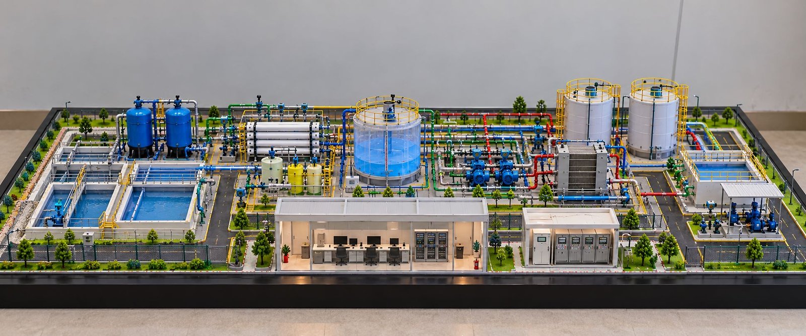
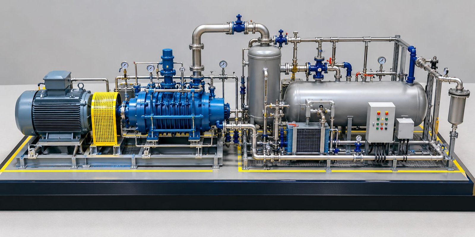
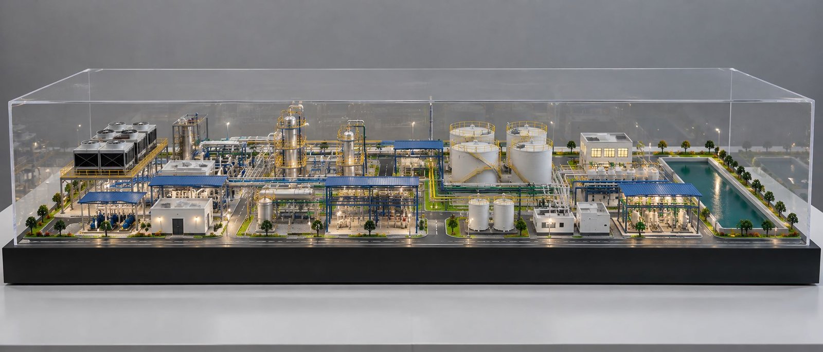
A Biogas Plant Scale Model gives a clear three-dimensional view of a complete industrial biogas facility. Instead of explaining the plant only through drawings or digital views, a physical model shows the major equipment, processing areas, pipelines, storage systems, roads, safety features and supporting structures together. As a result, architects, engineers, developers, project managers and clients can understand the proposed plant more easily.
A detailed biogas plant model can represent the complete movement of organic material through different sections of the facility. The layout can start with the raw material receiving area and continue through waste storage, feeding, pre-processing, anaerobic digestion, gas collection, purification, upgrading, storage and power generation. In addition, the model can show digestate handling, internal roads, pipe racks, safety railings, landscaping and lighting.
Biogas production also connects waste management with renewable energy. The International Energy Agency explains the role of biogas and biomethane in energy supply, waste management and emissions reduction. International Energy Agency – Biogases Similarly, the Food and Agriculture Organization describes how organic materials such as agricultural residues and animal waste can produce biogas through biological digestion in low-oxygen conditions. FAO – Biogas and Biomethane
What Is a Biogas Plant Scale Model?
A Biogas Plant Scale Model is a miniature physical representation of a real biogas production facility. A selected scale reduces the size of large industrial equipment while the model maker maintains the relationship between different plant sections.
For example, the model can represent large anaerobic digesters with cylindrical tanks and dome-shaped tops. Thin tubes can represent long gas pipelines, while miniature tanks, pumps, valves, conveyors and platforms can recreate the supporting process equipment.
Moreover, the model can show the complete plant layout in one view. This makes a Biogas Plant Model a useful visual communication tool rather than simply a decorative miniature.
Overall Biogas Plant Scale Model Layout
The overall layout plays an important role in a detailed biogas physical model. A good layout separates the major processing zones while keeping them connected through roads, pipelines and material-handling systems.
The featured industrial model uses a wide and low presentation format. This arrangement gives the major equipment enough space while keeping the overall model compact and easy to view.
Wide and Low Biogas Plant Model Layout
A wide model provides a better view of industrial equipment. Therefore, viewers can see the digesters, processing units, storage tanks, roads and buildings from a broader angle.
The rectangular baseboard also creates a clean boundary around the complete facility. In addition, balanced margins around the model improve the overall presentation.
Main Processing Zones of the Biogas Plant
A detailed model can include several major plant zones:
- Raw material receiving
- Organic waste storage
- Feeding and conveyor system
- Pre-processing
- Mixing and feed preparation
- Anaerobic digestion
- Biogas collection
- Gas purification
- Biogas upgrading
- Bio-CNG storage
- Power generation
- Digestate management
- Internal roads
- Safety and security
- Landscaping and lighting
As a result, the viewer can understand how each section connects with the next part of the facility.
Raw Material Receiving Area in a Biogas Plant Model
The raw material receiving area represents the starting point of the plant. Trucks can bring organic waste to this section before the material moves toward further processing.
A realistic Biogas Plant Model Making project can show a receiving shed, loading area, waste material, vehicles and access roads.
Organic Waste Receiving Area
The receiving shed can include a roof, structural columns and a defined loading space. A small loader or truck near the shed can demonstrate the movement of organic material.
Furthermore, the model maker can add small piles of feedstock near the receiving area. These details help viewers understand the first stage of the plant operation.
Waste Storage and Loading Area
The plant can include a temporary storage zone near the receiving section. The model can show this area with storage space, loading equipment and connecting access paths.
A miniature loader can also create a stronger sense of scale. Therefore, the receiving zone becomes a practical part of the overall industrial presentation.
Biogas Plant Model Making: Conveyor and Feeding System
The feeding system connects the receiving area with the processing section. Because this connection controls material movement, the model should show it clearly.
Material Feeding Conveyor
A miniature conveyor can use a narrow belt, support frame and small rollers. The model maker can connect the conveyor between the receiving area and the next processing zone.
In addition, side supports and a small loading hopper can add realistic industrial detailing.
Waste Transfer Equipment
The feeding section can also include hoppers, pumps, pipes and transfer equipment. Although these components remain smaller than the main digesters, they contribute significantly to the industrial appearance.
As a result, the Industrial Biogas Plant Model can communicate the material flow more effectively.
Pre-Processing Section of the Biogas Plant Scale Model
The feedstock can move through preparation and mixing equipment before it reaches the digesters. Therefore, the model can represent this section with tanks, pumps, pipes and supporting structures.
Mixing Tank and Feed Preparation
Mixing tanks can use cylindrical or rectangular shapes with pipe connections. These tanks represent the area where operators prepare the feed material before digestion.
Moreover, connecting pipes can show the movement of prepared material toward the anaerobic digesters.
Pumps and Process Equipment
Small pumps can sit near the tanks, while valves and short pipe sections can connect different pieces of equipment.
The model maker can also add support frames below selected vessels. This approach creates a more authentic industrial appearance.
Anaerobic Digester System in the Biogas Plant Model
Anaerobic digesters form one of the most important sections of a biogas facility. Consequently, these large tanks deserve strong visual attention in a Biogas Plant Scale Model.
Main Digester Tanks
The featured model can include several large cylindrical digesters near the centre of the plant. Their size immediately communicates their importance within the facility.
The tanks can have smooth cylindrical bodies with dome-shaped covers. Furthermore, connecting pipelines can link the digesters with the gas treatment area.
Digester Covers and Gas Collection
The dome-shaped covers represent the upper gas collection area. The model maker can connect gas pipes from the covers toward the purification and upgrading sections.
In addition, small pipe joints and vertical connections can create more realistic engineering details.
Digester Platforms and Safety Railings
Platforms around the digesters can include walkways, staircases and yellow safety railings. These features add depth and make the tanks look more like real industrial equipment.
At the same time, the platforms help viewers understand how workers can access the equipment during plant operation and maintenance.
Biogas Collection Piping in the Engineering Model
Pipelines form a major part of an industrial biogas facility. Therefore, a Biogas Engineering Model should clearly represent the main gas network.
Main Gas Pipelines
Gas pipelines can connect the digesters with purification and upgrading equipment. The model maker should arrange these pipes along logical routes.
Moreover, different pipe sizes can help viewers distinguish major lines from smaller process connections.
Pipe Supports and Connections
Small supports can hold elevated pipelines above the ground. Vertical sections can then connect equipment at different heights.
This type of detailing makes the engineering model more useful during technical presentations.
Biogas Purification System in the Biogas Plant Scale Model
Raw biogas can require treatment before the plant uses it for different applications. Therefore, the purification section deserves a dedicated place in the Biogas Plant Scale Model.
Gas Cleaning Equipment
The purification area can include process vessels, filters and vertical equipment. The model maker can arrange these units in a dedicated industrial zone.
Furthermore, several pipes can connect the treatment equipment with the main gas network.
Moisture Removal Equipment
Small vessels can represent moisture removal equipment. Short pipelines can connect these units with the main processing line.
Although these components remain relatively small, they add important technical detail to the model.
Process Vessels and Pipe Network
Several process vessels can stand together in the treatment section. The surrounding pipe network can then show the movement of gas between different equipment units.
As a result, the purification zone becomes visually connected to the main digestion system.
Biogas Upgrading Unit and Processing Equipment
The upgrading section creates another important zone within the plant. In the featured model, the BIOGAS UPGRADING UNIT can receive a dedicated position near the main processing equipment.
Upgrading Equipment
The upgrading area can include vertical vessels, horizontal equipment, pumps and connecting pipelines. The model maker can arrange these components with suitable spacing.
This arrangement keeps individual equipment visible and prevents the model from looking overcrowded.
Industrial Platforms and Safety Railings
Platforms can surround selected equipment, while yellow safety railings can define working areas. Ladders and stairs can connect different platform levels.
Therefore, these details add both realism and technical clarity to the industrial model.
Bio-CNG Plant Model: Storage and Fuel Section
A biogas facility can also include a Bio-CNG processing and storage area. The physical model can represent this section with a large vertical storage tank and supporting equipment.
Bio-CNG Storage Tank
The large white BIO-CNG STORAGE tank creates an important vertical element within the model. Its tall shape provides height variation while the rest of the plant maintains a low profile.
At the same time, small pipelines can connect the tank with the upgrading and gas-handling equipment.
Compressor and Gas Handling Equipment
Small compressor units and gas-handling equipment can sit close to the storage tank. These components help explain the relationship between gas treatment and storage.
Moreover, pipe connections can make the section look like a complete processing area.
Bio-CNG Filling Area
The model can include a small filling or fuel-handling zone near the storage section. A miniature vehicle can help explain the intended application of the processed gas.
As a result, the Bio-CNG Plant Model can visually connect gas processing, storage and vehicle use.
Biogas Power Generation Model
Biogas can also support power generation. For this reason, a dedicated generator area can add another important function to the physical model.
Generator and Engine Room
The generator can sit inside a small industrial building or shed. The model maker can add supporting pipes and equipment around the structure.
Furthermore, the generator building can sit close to the gas-processing area to create a logical visual connection.
Electrical and Control Building
A small control or electrical building can stand near the generator. Doors, windows, cable routes and external equipment can make the building more realistic.
Therefore, the model can represent both process equipment and the supporting infrastructure of the plant.
Digestate Management in the Biogas Plant
The digestion process also creates material that requires further handling. Therefore, the model can include a dedicated digestate management section.
Digestate Storage Tanks
Small or medium-sized storage tanks can stand near the digestion area. Connecting pipes can link these tanks with the processing section.
Moreover, the tanks should maintain logical spacing so the viewer can easily understand their position within the plant.
Slurry Transfer System
Pipes and pumps can represent digestate transfer between different areas. Small valves and pipe supports can add additional engineering details.
This approach allows the model to represent the complete plant rather than focusing only on gas production.
Industrial Biogas Plant Model: Pipe Racks and Equipment
Pipe racks add strong industrial character to a Biogas Plant Model. They can carry multiple pipelines between major processing areas.
Elevated Pipe Racks
Elevated pipes can cross internal roads or connect different equipment zones. Small structural frames can support these pipelines above ground level.
Furthermore, multiple pipe levels can create depth and make the model more visually detailed.
Pumps, Valves and Small Machinery
Small pumps, valves, motors and machinery can sit around the major equipment. Each component may look small, but together they create a convincing industrial environment.
In addition, these details help engineers and clients understand the relationship between major and supporting equipment.
Internal Roads and Vehicle Movement
A complete plant model should show vehicle movement. Therefore, internal roads should connect the main entrance with receiving, processing and storage areas.
Plant Access Roads
The model maker can create roads with a clean grey surface and clear boundaries. The road network should leave enough space around large equipment.
Moreover, turning areas can improve the realism of the receiving and loading sections.
Trucks and Material Handling Vehicles
Small trucks, loaders and other vehicles can stand at suitable locations. These vehicles provide a useful sense of scale.
As a result, the complete plant appears active and easier to understand.
Safety Systems in the Biogas Physical Model
Safety features add important technical detail to an industrial facility. Therefore, a detailed Biogas Physical Model can include several visible safety systems.
Safety Railings and Staircases
Yellow safety railings can surround elevated platforms and equipment areas. Small staircases can connect ground-level areas with platforms.
In addition, walkways can provide clear access routes around important equipment.
Boundary Wall and Security Fencing
A boundary wall or metal fence can surround the plant. This feature separates the industrial facility from the surrounding environment.
The fencing also helps define the actual site limits on the model baseboard.
Main Entrance and Security Gate
A dedicated security gate can sit near the front of the baseboard. The entrance can connect directly with the internal road network.
Consequently, the model gains a complete site-planning appearance.
Landscaping and Lighting in the Biogas Plant Scale Model
An industrial plant can still include controlled landscaping. Therefore, the model can use small trees, grass areas and green spaces around selected parts of the facility.
Green Areas and Trees
Small trees can line the boundary or occupy open spaces. However, the landscaping should remain secondary to the main industrial equipment.
A balanced approach keeps the plant realistic without making the model look like a residential landscape model.
Industrial Lighting Poles
Lighting poles can stand along roads and near major processing areas. These small elements add scale and improve the overall presentation.
Furthermore, miniature lighting can create an attractive display when the model uses an enclosure or presentation cabinet.
Baseboard Design for a Biogas Physical Model
The baseboard supports the entire project. Therefore, its design should receive the same attention as the miniature equipment.
Rectangular Baseboard
A rectangular baseboard works well for an industrial plant because it provides sufficient space for equipment, roads and landscaping.
The model maker should maintain balanced borders around the layout. As a result, the finished model looks clean from different viewing angles.
Low-Height and Wide Presentation Format
A wide and low format works especially well for an industrial feature model. It allows more equipment to remain visible within a single view.
Moreover, this arrangement creates a professional presentation without making the plant look unnecessarily tall.
Professional Model Finishing
Clean edges, accurate alignment, smooth surfaces and consistent colours can significantly improve the final result.
The model maker can also add a clear enclosure around the finished model when the project requires protection during transportation or long-term display.
Detailed Biogas Plant Model for Architectural Presentation
An architectural presentation model helps clients understand the relationship between buildings, equipment and the overall site.
For example, a project team can use the model to explain the position of digesters, processing units, storage tanks, roads and support buildings. Furthermore, viewers can inspect the facility from different angles.
Therefore, a detailed Biogas Plant Model can support project presentations before construction starts.
Biogas Engineering Model for Project Visualization
Engineering teams can use a physical model to communicate equipment relationships and plant layout. The model can show pipelines, process vessels, tanks, platforms and access areas together.
Moreover, a three-dimensional model provides a common visual reference for engineers, consultants and project managers.
This approach becomes especially useful when the project contains many interconnected systems that may appear complicated in two-dimensional drawings.
Biogas Plant Scale Model for Exhibition and Client Presentation
A high-quality Biogas Plant Scale Model can become an important exhibition display. Its physical presence attracts attention and allows visitors to understand the project quickly.
In addition, companies can use the model during client meetings, investor presentations, technical events and renewable energy exhibitions.
A clean baseboard, realistic equipment, professional finishing and well-planned landscaping can create a strong long-term display.
Custom Biogas Plant Model Making
Every biogas project can have different equipment, site dimensions, processing systems and plant capacities. Therefore, custom Biogas Plant Model Making should follow the project’s drawings and approved layout.
The model maker can select the scale according to the available display space. Likewise, the team can adjust equipment sizes and positions to match the project design.
A custom model can include:
- Anaerobic digesters
- Gas holders
- Storage tanks
- Gas purification systems
- Bio-CNG equipment
- Compressors
- Generator systems
- Pipe racks
- Pumps
- Conveyors
- Roads
- Industrial buildings
- Safety railings
- Security gates
- Landscaping
- Lighting systems
As a result, the finished model can provide a strong physical representation of the proposed facility.
Why Detailed Biogas Plant Models Are Important
A detailed model simplifies complex technical information. Instead of studying several drawings separately, viewers can observe the complete facility in one physical presentation.
Moreover, the model improves communication between technical and non-technical stakeholders. A client may not understand every engineering drawing, but a three-dimensional model can make the overall layout easier to explain.
Similarly, project managers can use the model during meetings to discuss equipment positions, site access, processing areas and supporting infrastructure.
Therefore, a Biogas Plant Scale Model can support design communication, project presentation, education and exhibition requirements.
Applications of a Biogas Plant Scale Model
A detailed biogas physical model can serve several purposes.
Project Presentation
Industrial Exhibition
Companies can display the model at renewable energy, engineering and industrial exhibitions.
Educational Demonstration
Schools, colleges and technical institutions can use smaller models to explain biogas production, waste management and renewable energy concepts.
Investor Presentation
A physical model can help investors understand the plant layout, processing zones and supporting infrastructure.
Engineering Discussion
Engineers can use the model as a visual reference during technical meetings and project reviews.
Corporate Display
Companies can display a professionally finished model in offices, reception areas, project rooms and presentation spaces.
Biogas Plant Model Making for Renewable Energy Projects
Renewable energy projects often contain several interconnected systems. A physical model brings these systems together in one clear visual presentation.
For example, the model can show organic waste receiving, digestion, gas treatment, upgrading, storage and power generation. In addition, it can show how roads, buildings and safety systems fit around the main process equipment.
As renewable energy projects continue to grow, detailed physical models can help companies communicate their concepts more effectively.
Conclusion
A Biogas Plant Scale Model provides a practical three-dimensional representation of a complete industrial biogas facility. The model can show everything from raw material receiving and waste handling to anaerobic digesters, gas collection, purification, upgrading, Bio-CNG storage, power generation and digestate management.
Furthermore, pipelines, pipe racks, pumps, conveyors, roads, trucks, safety railings, buildings, landscaping and lighting add valuable physical detail. The rectangular baseboard and wide, low-height format also create a professional presentation suitable for client meetings, exhibitions and project displays.
Whether a project needs an architectural model, engineering model, educational display or industrial presentation model, a detailed biogas plant model can make complex information easier to understand. With accurate layout planning, realistic equipment and clean finishing, the model can effectively communicate the complete plant concept.
Final Thought
A professionally designed Biogas Plant Scale Model turns a complex renewable energy facility into a clear and engaging three-dimensional presentation. Accurate equipment placement, realistic industrial details and clean finishing can make the model useful for presentations, exhibitions, engineering discussions and long-term display.