Shell Roof Structure Model: Design, Components and Engineering Applications
Introduction to Shell Roof Structure Models
A shell roof structure uses a curved surface to cover large spaces with fewer internal columns. Its unique shape helps distribute loads across the roof and transfer them to the supporting structure. As a result, architects and engineers often consider shell roofs for buildings that need wide, open interiors and an attractive architectural design.
A Shell Roof Structure Model presents this roof system as a physical three-dimensional model. It helps architects, civil engineers, structural consultants, builders and students understand the roof geometry, support arrangement and construction details.
For example, airports, exhibition centres, sports complexes, auditoriums, railway stations and industrial buildings may use curved or shell-like roof systems. These buildings often require large covered areas, so the roof design plays an important role in their overall appearance and function.
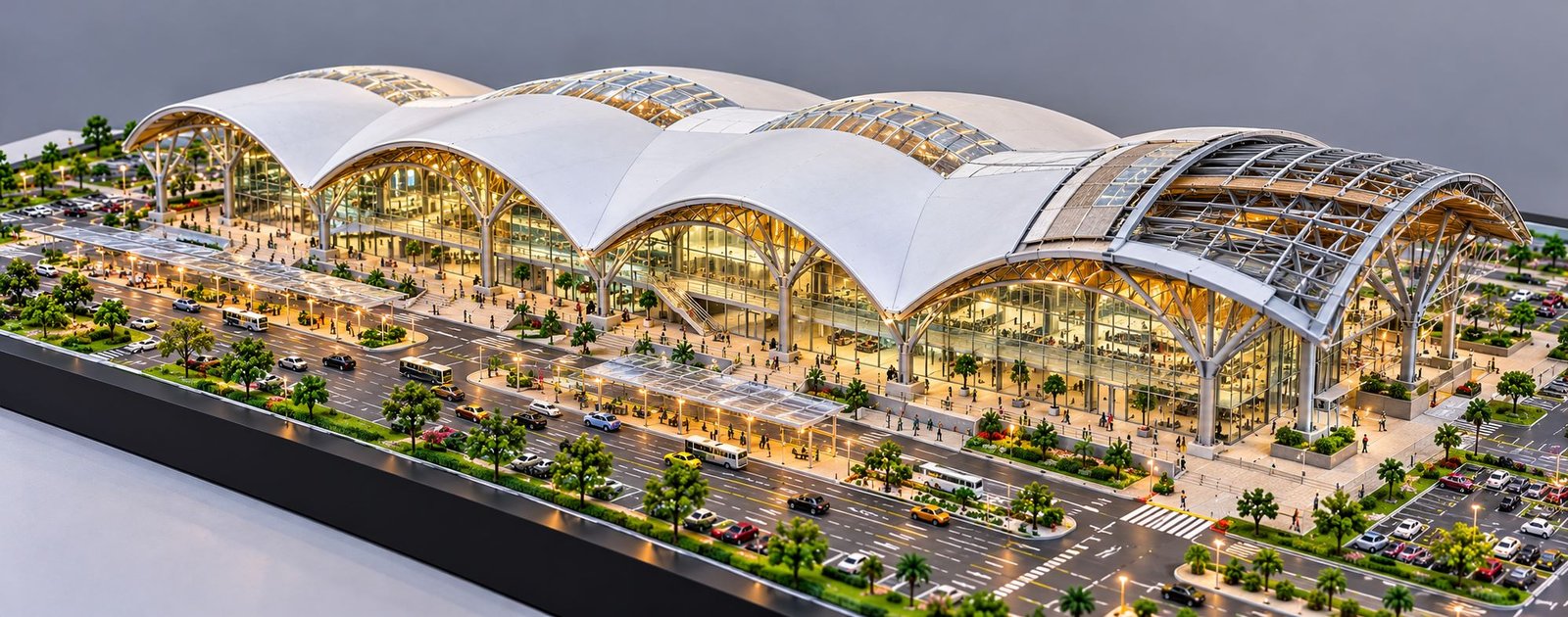
Furthermore, a professionally made shell roof model can show the complete building or focus on the structural roof system. Depending on the project requirements, it may include curved roof panels, structural ribs, support columns, skylights, glass façades, foundations and surrounding site development.
In addition, a physical engineering model helps people understand complex designs more easily than drawings alone. Viewers can examine the roof shape, supporting members and overall layout from different angles.
What Is a Shell Roof Structure?
A shell roof is a roof system that uses a curved or specially shaped surface to carry and distribute loads. Its geometry helps the structure transfer forces towards the supports, edges and foundations.
Designers may use reinforced concrete, steel, timber, aluminium or composite materials to construct shell roof systems. However, the final choice depends on the required span, structural design, construction method, environmental conditions and project budget.
In a shell roof engineering model, the main objective is to show how the curved surface relates to its supporting structure. Therefore, the model should clearly present the roof profile, support locations and important structural components.
Importance of Curved Roof Geometry
Curved roof geometry affects both the appearance and structural behaviour of a building. Unlike a simple flat roof, a shell surface can distribute forces through its shape.
However, the actual performance depends on the surface geometry, material properties, thickness, support conditions and applied loads. Consequently, engineers must analyse these factors before approving the final design.
A physical model can represent several common shell roof forms.
- Barrel Shell Roof: This roof extends along one direction and creates a curved vault. For example, designers may use it for industrial halls, warehouses and exhibition buildings.
- Dome Shell Roof: This form curves in several directions around a central area. As a result, it suits auditoriums, sports facilities and assembly halls.
- Folded Plate Roof: This system connects several flat surfaces to create a rigid roof form.
- Hyperbolic Paraboloid Roof: This saddle-shaped surface creates an interesting architectural form and can use straight boundary members.
- Elliptical Shell Roof: This roof uses an elongated curved profile to create a distinctive appearance.
- Freeform Shell Roof: This customised surface combines different curves to meet specific architectural requirements.
Each roof form has different structural and fabrication requirements. Therefore, the physical model should follow the selected design rather than combine unrelated features.
Why Shell Roof Structure Models Matter in Engineering
A shell roof model turns a complicated structural concept into a three-dimensional presentation. Consequently, viewers can understand the relationship between the roof surface, supporting framework and building layout more easily.
Visualising Complex Roof Geometry
Architectural plans and elevations provide important information, but they may not fully communicate a complex curved surface.
A physical shell roof model shows the roof height, curvature, repeated bays and overall proportions. For instance, an exhibition centre may contain several connected roof sections. The model can show how these sections align and how their curves create a continuous roof.
Furthermore, viewers can inspect the structure from different angles. This makes the model useful during design reviews and technical presentations.
Explaining Structural Load Transfer
Another important purpose of the model is to explain the basic load path.
The roof transfers its loads through the shell surface and supporting system towards the foundations. Depending on the design, the structure may experience compression, tension, bending and shear forces.
For this reason, the model can highlight the roof surface, primary ribs, edge beams, columns, connections and foundations. These details help viewers understand the intended structural arrangement. However, a physical model alone cannot prove that a full-size building will safely carry its design loads.
Supporting Architectural Presentations
Architects and developers often need to present building designs before construction begins. A physical model gives clients a clear view of the proposed structure.
Moreover, the model can show the relationship between the roof, entrances, glass façades, pedestrian areas and surrounding landscape. As a result, it becomes useful for design reviews, client meetings and project presentations.
Main Components of a Shell Roof Structure Model
A professional model should include the components that best explain the roof’s shape, construction and supporting arrangement. Nevertheless, the required level of detail depends on the project’s purpose.
Shell Roof Surface
The shell surface forms the main architectural feature of the model. Its curvature determines the roof’s appearance and helps explain the intended structural form.
Model makers may use thin plastic sheets, acrylic, mouldable materials, resin or other suitable materials to create the surface.
The finished roof should have smooth curves, clean edges and consistent proportions. In addition, repeated roof bays should follow the same geometry wherever the design requires them.
Primary Structural Ribs
Primary ribs support the roof in systems that use a ribbed framework. These members may follow the roof curve and transfer loads towards columns, arches or other supports.
Model makers can use thin metal profiles, shaped strips or fabricated components to represent these members. However, their placement should remain visible without making the model look crowded.
Not every shell roof uses separate ribs. In fact, some thin-shell systems rely mainly on the surface itself to carry loads. Therefore, the model should reflect the supplied structural design.
Secondary Structural Members
Secondary members support roof panels or form part of the underlying framework. Depending on the design, they may include purlins, secondary beams, bracing and connecting members.
A model can show these components beneath the roof surface or expose them in a selected section. Consequently, viewers can distinguish the roof covering from the supporting framework.
Support Columns
Columns transfer roof loads towards the foundations. In addition, their positions affect the interior space and the building’s appearance.
A shell roof model may feature straight steel columns, reinforced concrete columns, branching Y-shaped columns or inclined supports.
The model should maintain consistent column spacing and show how the roof connects to each support. As a result, the roof will appear properly integrated with its supporting system.
Edge Beams and Ring Beams
Some shell roof systems use edge beams or ring beams to support the roof boundaries and resist forces associated with the selected geometry.
For example, certain dome structures use ring beams around their perimeter. Meanwhile, other roof forms may use edge beams along their boundaries.
The model should include these members when the design requires them. Moreover, their positions must match the roof profile and support arrangement.
Foundations and Base Connections
Foundations transfer loads from the supporting structure into the ground. In a physical model, they may appear as concrete footings, foundation blocks or simplified foundation layouts.
Model makers can also show base plates, anchor bolts and column connections when these details are important to the presentation.
For a general architectural model, simplified foundations may be sufficient. However, an engineering demonstration may require more visible connection details.
Roof Covering and Waterproofing
A roof assembly may contain a structural surface, waterproofing membrane, insulation and an external finish. These layers serve different purposes and should not be confused with the primary structural system.
A partial cutaway can show the roof layers in a clear sequence. In this way, the model provides more information without exposing every layer across the complete roof.
Skylights and Roof Openings
Skylights allow natural light to enter the building. Designers may incorporate them as glazed strips, individual openings or raised roof sections.
Their locations must match the architectural design and structural framework. Furthermore, large openings may require additional framing, depending on the roof system.
Model makers can use transparent or translucent sheets to represent skylights. In addition, repeated openings should remain aligned and proportional to the roof bays.
Drainage and Rainwater Collection
Curved roofs need a suitable drainage system to manage rainwater and prevent unwanted water accumulation.
Depending on the roof geometry, the system may include gutters, valleys, outlets, downpipes or concealed drainage channels.
A shell roof model can show the general drainage direction and selected collection points. However, engineers must determine the actual drainage arrangement through appropriate design calculations.
Types of Shell Roof Structure Models
Different roof shapes require different modelling techniques. Therefore, selecting the right type helps the model communicate the intended engineering concept.
Barrel Shell Roof Model
A barrel shell model features a curved roof that extends along a longitudinal direction. It may represent one continuous vault or several repeated bays.
This type of model suits industrial halls, warehouses, exhibition buildings and transport facilities. Moreover, the model should clearly show the roof’s curvature, end supports and relationship between adjacent sections.
Dome Shell Roof Model
A dome shell model represents a roof that curves in several directions. Depending on the design, the dome may be spherical, elliptical or based on another geometric form.
A physical model can show the curved surface, perimeter supports and any central openings. As a result, viewers can understand the overall geometry more easily.
Hyperbolic Paraboloid Roof Model
A hyperbolic paraboloid roof creates a saddle-shaped surface with curvature in opposite directions.
This roof form is particularly useful for demonstrating the relationship between geometry and structural design. Consequently, the model should maintain the correct saddle profile rather than resemble a flat canopy.
Folded Plate Roof Model
A folded plate roof consists of connected flat surfaces that create a three-dimensional structural form.
The model should show the folds, joints and supporting members clearly. In addition, accurate panel angles are essential for a professional finish.
Freeform Shell Roof Model
A freeform shell roof uses a customised surface that may combine several curves or transition between different shapes.
These designs often appear in distinctive public buildings and large architectural projects. However, their complex geometry requires careful fabrication.
Digital modelling and templates can help maintain accuracy before the model maker begins physical construction.
Materials Used in Shell Roof Model Making
The choice of material affects the model’s surface quality, weight, strength and level of detail.
Acrylic and Transparent Plastics
Acrylic works well for skylights, glass façades and selected transparent components. It gives the model a clean architectural appearance.
However, scratches, rough edges and visible adhesive marks can reduce the quality of the finished model. Therefore, careful cutting and assembly help maintain a professional finish.
PVC and Lightweight Sheets
PVC and other lightweight sheets can represent smooth roof surfaces, panels and architectural components.
These materials are useful when the design requires clean edges and repeatable shapes. Nevertheless, the model maker should select a suitable thickness for the required curvature.
Foam and Mouldable Materials
Foam-based materials help model makers develop curved shapes and create prototypes. They can shape and smooth the surface before applying the final finish.
For example, this method works well for custom roof profiles that require careful shaping.
Metal Rods and Profiles
Small metal rods and profiles can represent structural ribs, columns, braces and exposed frameworks.
These components are particularly useful when the model must show how the roof connects to its supporting structure. Furthermore, they create a clear distinction between the roof surface and its framework.
Resin and 3D-Printed Components
Resin and 3D printing can produce complex joints, custom connectors and repeated structural components.
For example, a model maker can fabricate a custom connection where several curved ribs meet a support column. Similarly, these methods can reproduce unusual roof geometries.
Baseboard and Presentation Materials
A rigid baseboard provides a stable platform for the model. A wide rectangular baseboard often suits long-span shell roof structures because it provides sufficient space for the building and selected surrounding features.
The base may include access roads, entrance zones, parking areas and landscaping. Nevertheless, these features should support the main presentation rather than distract viewers from the roof.
Structural Detailing and Load Transfer
A shell roof model should explain the basic engineering principles without suggesting that a miniature model behaves exactly like a full-size structure.
Dead Loads
Dead loads include the permanent weight of the roof and its fixed components. These may include the shell surface, insulation, waterproofing, ceiling systems and permanently installed equipment.
The model can identify the roof and supporting members as the main components of the permanent structural system.
Live Loads and Maintenance Loads
Depending on the design, maintenance personnel, temporary equipment and other imposed loads may affect the roof.
The model can show maintenance walkways or access areas if the supplied design includes them. However, the actual design must account for the relevant loading requirements.
Wind Loads
Wind creates pressure and suction on roof surfaces. Curved roofs may experience complex aerodynamic effects, especially near edges and transitions.
Therefore, engineers must consider the relevant wind conditions, roof shape and connection design. A physical model can communicate the geometry but cannot independently verify wind resistance.
Rainwater Loads
Water accumulation can increase roof loading. Poor drainage may create additional demands, particularly where the roof geometry allows water to collect.
For this reason, the model should show the intended drainage concept where it forms an important part of the design.
Seismic Considerations
In earthquake-prone regions, engineers must consider the supporting structure, connections and foundations under the applicable seismic requirements.
A model can illustrate the arrangement of columns, braces and connections. Nevertheless, structural analysis remains necessary to assess actual seismic performance.
Designing a Shell Roof Model for a Large Building
A successful model begins with a clear understanding of the building’s purpose, roof geometry and presentation requirements.
Establish the Building Layout
First, determine the overall length, width and approximate height of the building. For a wide-span structure, a long rectangular baseboard can accommodate the building footprint and selected surrounding features.
The roof should occupy a prominent part of the baseboard. Meanwhile, columns, entrance areas and access routes should maintain suitable proportions without overcrowding the layout.
Select the Appropriate Scale
The model scale depends on the building size, available display area and required level of detail.
A larger scale makes individual connections easier to show. In contrast, a smaller scale allows the model maker to represent a larger building and more of its surroundings.
The scale should remain consistent across the roof, columns, façades, vehicles and landscape elements.
Develop the Roof Geometry
The model maker should establish the roof shape before fabricating the supporting structure.
CAD drawings, three-dimensional modelling and physical templates can help control the dimensions and curvature. For repeated roof bays, check the profile and spacing before fabrication begins.
Coordinate the Structural Supports
Next, position the columns, ribs, edge beams and foundations according to the design.
Check the alignment before attaching the roof surface. Consequently, this process helps prevent visible gaps, irregular supports and unsupported sections.
Integrate the Building Envelope
The façade may use glass, solid wall panels or a combination of materials.
Transparent sheets can reveal selected interior areas and show how the roof relates to the occupied space. In addition, the entrance and circulation areas should remain consistent with the building layout.
Complete the Site Presentation
The surrounding site may include access roads, pedestrian paths, parking spaces, landscaping and entrance canopies.
These elements add context to the physical model. However, the roof structure should remain the main visual feature.
Construction Process for a Physical Shell Roof Model
A systematic workflow helps model makers maintain accuracy and produce a clean finish.
Prepare Drawings and Templates
Begin with the roof plan, elevations, sections and relevant structural drawings. These documents establish the dimensions and locations of the supports and openings.
For complex curved surfaces, prepare accurate templates or digital fabrication files. This preparation helps reduce errors during assembly.
Fabricate the Baseboard
Create a stable baseboard with enough space for the building footprint and selected site features.
Check that the base is flat and rigid before installing the structural components. Otherwise, an uneven base may affect the alignment of the finished model.
Build the Supporting Framework
Fabricate the columns, primary ribs, secondary members and edge supports according to the design.
Check their spacing and alignment before installing the roof surface. In addition, the framework must remain stable throughout assembly.
Form the Shell Surface
Create the curved roof using the selected material and fabrication method.
For repeated roof bays, maintain a consistent profile. Furthermore, keep the joints neat and follow the intended roof geometry.
Install Skylights and Openings
Fit transparent panels and roof openings after confirming their dimensions and positions.
Check that the openings align with the structural framework and do not create unintended gaps. As a result, the roof will have a cleaner and more realistic appearance.
Complete the Façade and Foundations
Install the building envelope, entrances, column bases and foundation details.
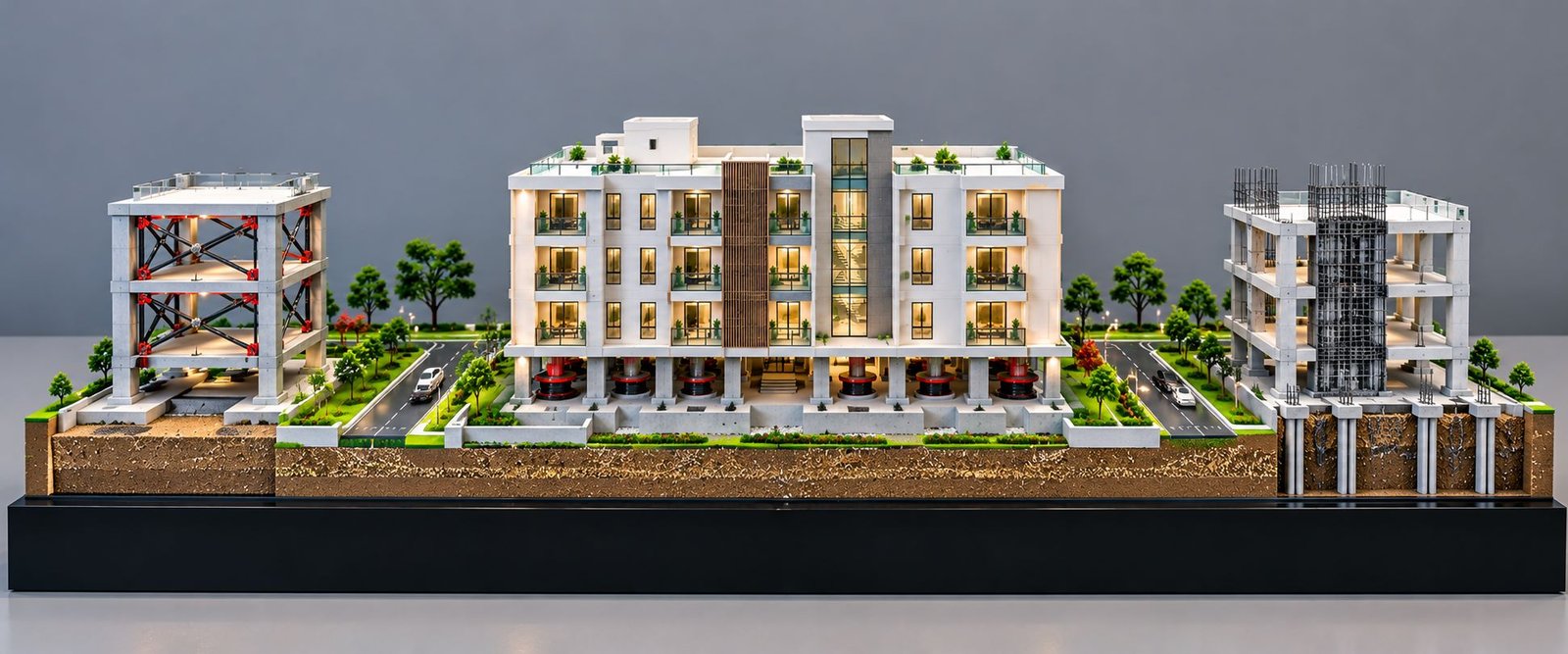
If the presentation requires a structural cutaway, expose a selected section while keeping the rest of the roof complete. This approach shows the framework without compromising the overall architectural form.
Apply the Final Finish
Complete the roof finish, road markings, landscape elements and other selected details.
Finally, inspect the model from the front, sides and elevated angles. This review helps confirm that the roof shape and supporting structure remain clearly visible.
Common Challenges in Shell Roof Model Making
Shell roof models require careful control of geometry and alignment. However, systematic planning can help reduce common fabrication problems.
Maintaining Consistent Curvature
Small differences between repeated roof sections can make the surface look uneven. Accurate templates, jigs and digitally fabricated components help maintain a consistent profile.
Preventing Structural Misalignment
Misaligned columns and ribs can distort the roof’s appearance. Therefore, check the supporting framework before fixing the final roof surface.
Avoiding Excessive Detailing
Too many decorative elements can make the engineering system difficult to understand. Instead, keep the roof geometry, supporting members and important construction details as the main focus.
Balancing Structural Visibility and Architectural Appearance
A complete roof presents the finished architectural form, while an exposed framework reveals the underlying structure.
For a detailed presentation model, a partial cutaway can show both aspects. In this way, the model preserves the building’s overall appearance while explaining the supporting system.
Protecting Delicate Components
Thin roof surfaces, transparent panels and slender structural members may suffer damage during transportation.
A rigid baseboard and carefully designed connections help protect the model. Furthermore, detachable components can make transport and maintenance easier when the design permits them.
Applications of Shell Roof Structure Models
Shell roof models serve several sectors across architecture, construction and engineering.
Airports and Transportation Terminals
Large terminals need wide roof spans, open circulation areas and distinctive architectural forms.
A physical model can show the relationship between the roof, passenger areas, entrance zones, columns and glazed façades. Moreover, it can help project teams communicate the overall design during planning meetings.
Exhibition and Convention Centres
Convention buildings require flexible interiors and roof systems that cover large areas.
A model can communicate the repeated structural bays, roof arrangement and overall building footprint. Consequently, clients can understand the proposed architectural form more clearly.
Sports Complexes and Stadiums
Sports facilities may use curved roofs, long-span trusses, shell surfaces or combined structural systems.
The model can illustrate the roof, seating areas, concourses and supporting columns. In addition, it can present the relationship between the roof and the surrounding site.
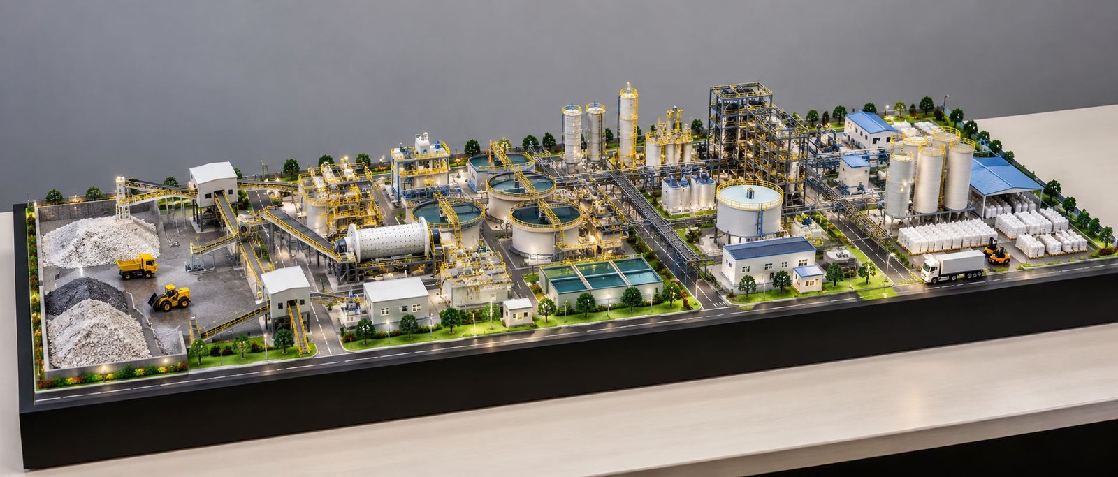
Industrial and Manufacturing Buildings
Industrial buildings may use curved or shell-like roofs to cover large production areas.
A model can show the roof configuration, support locations, ventilation openings and building access. However, the final structural arrangement must follow the actual engineering design.
Auditoriums and Cultural Buildings
Auditoriums and cultural centres often use distinctive roof geometries to create a strong architectural identity.
A physical model can show the relationship between the roof surface, supports and surrounding public areas. As a result, the architectural concept becomes easier to communicate.
Educational and Research Projects
Civil engineering and architecture students can use shell roof models to study surface geometry, structural forms and construction methods.
These models are suitable for academic demonstrations, design studios, engineering exhibitions and research presentations. Furthermore, they can help explain the differences between several roof systems.
Benefits of a Professionally Made Shell Roof Scale Model
A professionally made model combines technical communication with a clear visual presentation.
It helps viewers understand the building’s proportions, roof shape and supporting arrangement. Moreover, a three-dimensional model allows teams to discuss design alternatives and review the relationship between different components.
For contractors and developers, a physical model can support project presentations and coordination meetings. Similarly, architects and structural engineers can use it to explain the intended arrangement to clients who may not be familiar with technical drawings.
The main benefit is clarity. A well-designed model presents important structural features in a format that people can examine from different angles.
However, the model should complement technical drawings and engineering calculations rather than replace them.
Choosing a Shell Roof Model Making Company
Selecting an experienced model maker is important when the roof geometry is complex or the model will support a professional presentation.
The team should understand architectural drawings, roof profiles and the relationship between the surface and its supporting structure. In addition, it should be able to fabricate curved components with consistent dimensions.
Before choosing a model maker, review previous architectural and engineering projects. Pay particular attention to models that feature large-span roofs, repeated bays, exposed structural frameworks and curved surfaces.
Furthermore, discuss the model scale, baseboard dimensions, material selection, required detailing and presentation purpose before production begins.
A clear project brief helps the model maker follow the supplied design and avoid adding unsupported structural features.
Shell Roof Structure Model Making by PAL Design Models
PAL Design Models provides architectural and engineering scale model making services for projects that need clear three-dimensional presentation.
A shell roof structure model can represent the building’s overall form, curved roof profile, supporting columns, structural ribs, façade arrangement and selected construction details.
Depending on the project requirements, the model may feature a wide rectangular baseboard, a low-profile building layout, skylights, exposed framework and a partial cutaway.
For architectural presentations, the model can focus on the finished roof and building appearance. In contrast, an engineering presentation can make the supporting members and selected connections more visible.
The final approach depends on the supplied drawings, dimensions and intended use of the model.
Architects, structural consultants, builders, developers, educational institutions and engineering teams can use physical scale models to communicate complex roof concepts more effectively.
To develop a project-specific shell roof model, PAL Design Models can review the available drawings, dimensions, preferred scale and presentation requirements before fabrication.
Visit https://paldesignmodels.com/ to learn more about architectural and engineering model making services.
Frequently Asked Questions About Shell Roof Structure Models
What is a shell roof structure model?
A shell roof structure model is a physical three-dimensional representation of a building roof that uses a curved or specially shaped surface. It can show the roof profile, supports, ribs, skylights, façades and foundations.
Which materials are suitable for shell roof model making?
Suitable materials may include acrylic, PVC sheets, lightweight mouldable materials, resin, 3D-printed components and metal profiles. However, the choice depends on the roof geometry, required detail and final finish.
Can a shell roof model include exposed structural details?
Yes. The model can include exposed ribs, secondary members, columns, edge beams, connections and selected foundation details. Moreover, a partial cutaway can reveal the framework while preserving the finished roof elsewhere.
Which buildings use shell roof structures?
Shell roof forms may appear in exhibition centres, airport terminals, sports facilities, auditoriums, industrial buildings and other large-span structures. Nevertheless, the appropriate roof system depends on the project’s architectural and structural requirements.
Can the model use a wide rectangular baseboard?
Yes. A wide rectangular baseboard can accommodate a long-span building, repeated roof bays, entrances and selected site features. Its dimensions should suit the building footprint, model scale and available display area.
How does a shell roof differ from a conventional roof?
A shell roof uses its surface geometry to help carry and distribute loads. In comparison, a conventional roof may rely more directly on beams, trusses, slabs or other framing systems. The actual structural behaviour depends on the specific design.
Can a shell roof model support an engineering presentation?
Yes. It can demonstrate the roof shape, support arrangement, structural framework and selected construction details. However, engineers must use appropriate calculations and analysis to establish the safety of a full-size structure.
Conclusion
A Shell Roof Structure Model presents the relationship between architectural form and structural engineering in a clear, three-dimensional format. Its curved surfaces, supporting framework, columns, skylights and foundations help viewers understand the main features of a complex building.
A successful model combines accurate geometry, suitable materials, consistent fabrication and a systematic layout. For large-span buildings, a wide rectangular baseboard and a relatively low-profile presentation can create a balanced composition while keeping the roof structure visible.
Whether the project involves an exhibition centre, industrial hall, transport terminal or educational demonstration, the model should follow the actual design requirements. Therefore, careful coordination between the drawings, roof geometry and supporting components helps create a professional presentation.
PAL Design Models can develop project-specific architectural and engineering scale models based on the drawings, dimensions and presentation requirements provided by the client.