Jet Engine Cutaway Model Making: Detailed Engineering Scale Model
A jet engine is one of the most sophisticated examples of modern mechanical and aerospace engineering. It converts the energy released by burning fuel into the thrust required to propel an aircraft. Inside the engine, multiple components work together, including the air intake, compressor stages, combustion chamber, turbine assembly, shafts, and exhaust nozzle. Understanding how these components interact requires a clear view of the engine’s internal construction.
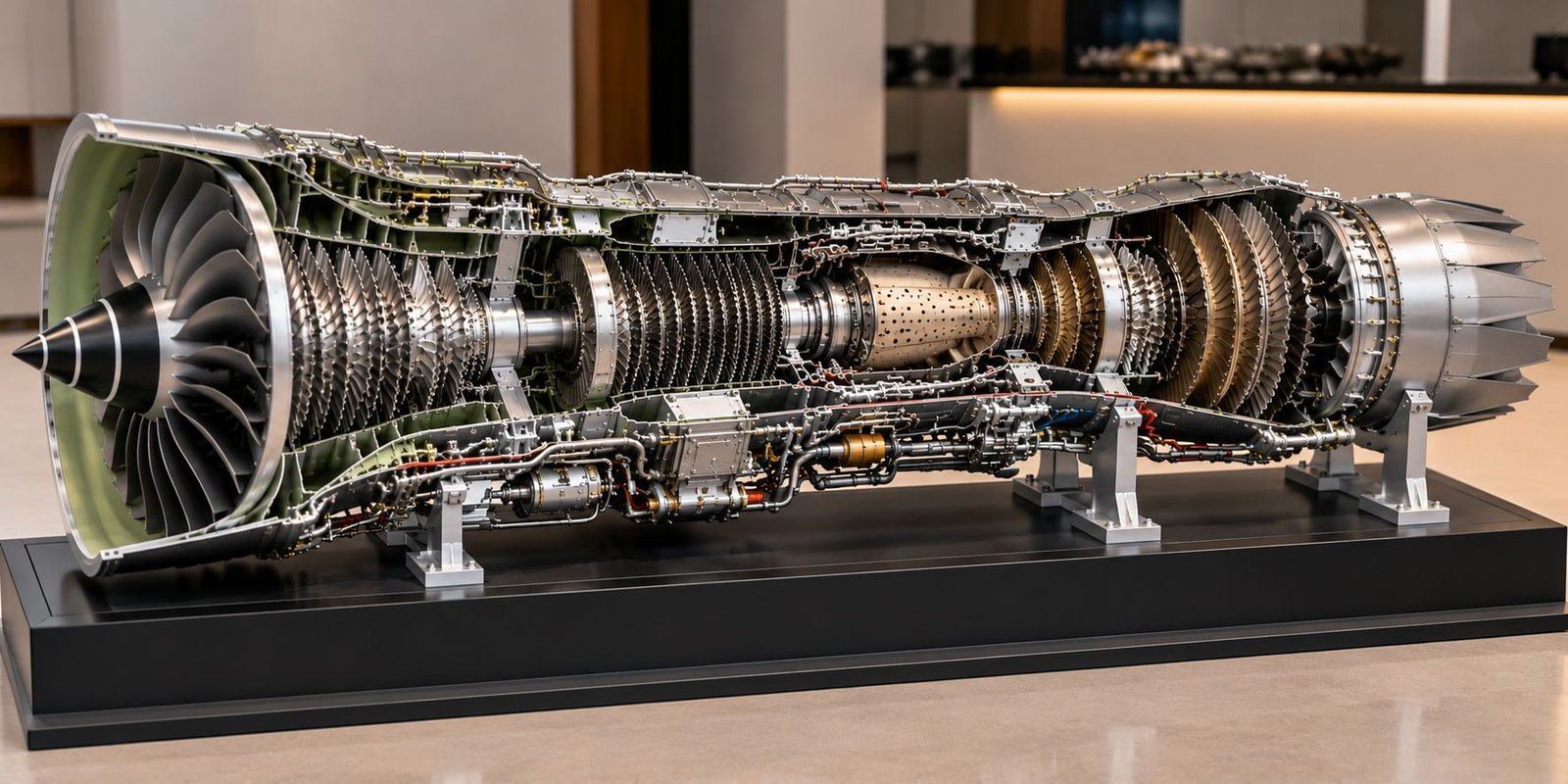
A Jet Engine Cutaway Model provides a practical way to visualize this complex engineering system. Unlike a conventional engine model with a completely closed outer casing, a cutaway model exposes selected internal sections. As a result, viewers can examine the compressor blades, combustion chamber, turbine stages, connecting shafts, and exhaust arrangement within one physical structure.
At PAL Design Models, engineering model-making services can support the presentation of complex mechanical systems through detailed physical scale models. A professionally fabricated jet engine model can combine realistic component geometry, metallic finishes, carefully arranged internal parts, and a sturdy display base.
Moreover, a wide and low-height presentation design can show the complete engine horizontally, from the front intake to the rear exhaust nozzle. This arrangement makes the internal components easier to inspect and works well for engineering exhibitions, technical training, educational displays, and aerospace project presentations.
This blog explains the construction, components, design considerations, fabrication methods, applications, and benefits of a detailed Jet Engine Cutaway Model.
What Is a Jet Engine Cutaway Model?
A Jet Engine Cutaway Model is a physical representation of a jet engine in which selected portions of the external casing are removed or opened to reveal the internal mechanisms. It allows viewers to examine the engine’s major components and understand their arrangement along the central axis.
Depending on the project requirements, the model can represent a turbojet, turbofan, or another jet engine configuration. Each design has its own characteristics, so the model should follow the selected engine type rather than combine unrelated components.
For example, a turbofan cutaway model can display a large front fan, multiple compressor stages, a combustion chamber, turbine assemblies, and an exhaust system. In contrast, a simplified turbojet model may emphasize the compressor, combustion chamber, turbine, and exhaust nozzle.
A professional physical model should maintain realistic proportions and a clear relationship between individual components. Furthermore, the cutaway sections should expose important engineering details without making the engine appear incomplete or incorrectly assembled.
Purpose of a Jet Engine Cutaway Model
The main purpose of this model is to explain the internal construction of a jet engine in a visual and understandable format.
Engineering students can use it to study the arrangement of rotating and stationary components. Aerospace training centres can display it during technical demonstrations, while engineering companies can use it to present mechanical design concepts.
In addition, the model can support discussions about airflow, compression, combustion, turbine operation, and thrust generation. However, a static cutaway model explains the physical arrangement rather than independently demonstrating the engine’s complete operating performance.
Importance of Physical Jet Engine Model Making
Jet engines contain many closely arranged components inside a relatively compact casing. Technical drawings can explain their geometry, but a three-dimensional physical model provides a more direct understanding of their spatial relationships.
Clear Visualization of Internal Components
A cutaway model exposes selected internal sections that an enclosed engine would hide. Consequently, viewers can see the compressor stages, combustion liner, turbine blades, shafts, and exhaust components together.
This arrangement makes the model useful for presentations where the internal engineering design matters as much as the exterior appearance.
Improved Engineering Education
Engineering students often study jet engines through diagrams, textbooks, simulations, and technical illustrations. A physical model adds a tangible reference to this learning process.
For example, students can compare the compressor and turbine sections, examine the position of the combustion chamber, and follow the engine’s overall flow path.
Moreover, a model with clearly separated components can help instructors explain the functions of different engine sections during classroom demonstrations.
Professional Project Presentation
A detailed Jet Engine Cutaway Model can serve as a centrepiece in aerospace exhibitions, engineering laboratories, corporate offices, and technical training facilities.
Realistic metallic finishes, accurate blade arrangements, clean structural supports, and a professional baseboard create a convincing presentation. Nevertheless, the model should prioritize engineering accuracy rather than excessive decorative lighting or bright colours.
Major Components of a Jet Engine Cutaway Model
A high-quality model should show the engine’s major components in their correct sequence. The precise arrangement depends on the engine configuration selected for the project.
Air Intake and Front Fan
The air intake guides incoming air into the engine. In a turbofan engine, the front fan accelerates a large volume of air, with part of the flow entering the engine core and the remaining flow bypassing it.
A physical model can represent the intake casing, central spinner, fan blades, and surrounding structure.
The fan blades should have consistent spacing, realistic curvature, and a suitable metallic finish. In addition, the front opening should provide a clear view of the fan assembly.
For a wide, low-height display, the intake should remain prominent without becoming disproportionately large compared with the rest of the engine.
Low-Pressure Compressor
The low-pressure compressor increases the pressure of air entering the engine core. Depending on the design, it contains multiple rotating rotor stages and stationary stator rows.
A detailed cutaway model can show the blade rows, central shaft, casing, and progressively arranged compressor sections.
Each stage should maintain a consistent orientation and realistic spacing. Furthermore, the model should distinguish rotating blades from stationary components so viewers can understand the basic construction.
High-Pressure Compressor
The high-pressure compressor raises the air pressure further before the air reaches the combustion chamber.
This section typically contains several closely spaced blade stages. Therefore, accurate detailing is particularly important because the compressor forms one of the most visually complex areas of a jet engine cutaway model.
The model can include metallic rotor blades, stator vanes, shaft sections, casing supports, and selected internal passages.
A partially opened casing provides a clear view of these components. Moreover, carefully finished blade surfaces improve the realistic appearance of the engine.
Combustion Chamber
The combustion chamber receives compressed air and mixes part of it with fuel. The resulting combustion process releases energy and produces high-temperature gases that flow toward the turbine.
A cutaway model can reveal the combustion liner, fuel injector locations, surrounding casing, and selected cooling passages.
A bronze, steel, or heat-resistant metallic finish can distinguish this section from the cooler-looking compressor components. However, the colour should remain realistic rather than excessively bright.
The combustion chamber should also connect logically to the compressor outlet and turbine inlet. This arrangement helps viewers understand the engine’s continuous internal flow path.
High-Pressure Turbine
The high-pressure turbine extracts energy from the hot gases to drive the high-pressure compressor through a shaft.
This assembly generally contains turbine rotor blades and stationary nozzle guide vanes. The model should show these components in the correct sequence.
Detailed blade geometry, metallic surface finishes, and visible shaft connections can make the section easier to recognize.
Furthermore, the turbine should remain clearly separated from the combustion chamber in the cutaway view, while maintaining the correct overall relationship between the two sections.
Low-Pressure Turbine
The low-pressure turbine extracts additional energy from the gas flow and drives the low-pressure compressor or fan through its corresponding shaft arrangement.
A detailed model can include multiple turbine stages, rotor blades, stationary vanes, and connecting shaft components.
The low-pressure turbine often provides a visually rich section because of its repeated blade rows. Therefore, consistent spacing and alignment are essential.
The model should follow the selected engine’s configuration rather than assume that every jet engine uses the same number of turbine stages.
Exhaust Duct and Nozzle
The exhaust system directs the gas flow toward the rear of the engine. Depending on the design, the nozzle may have a fixed or variable geometry.
A physical model can show the exhaust duct, nozzle casing, internal surfaces, and rear outlet.
The nozzle should maintain a realistic relationship with the turbine section and the engine’s central axis. In addition, its outer surface should use a consistent metallic finish.
A clean exhaust opening completes the model and makes the overall front-to-rear arrangement easier to understand.
Central Shafts and Bearings
Shafts transmit rotational power between different engine sections. Bearings support rotating assemblies and help maintain their alignment.
The cutaway design can expose the main shaft arrangement, selected bearing supports, connecting structures, and mounting details.
These components are especially important in an engineering-focused model because they demonstrate how the compressor and turbine assemblies connect mechanically.
Where the scale allows, the model can include retaining rings, bearing housings, support brackets, and shaft collars.
Engine Casing and Structural Supports
The engine casing encloses and supports the internal assemblies. In a cutaway model, selected casing sections remain in place while other portions expose the internal components.
A realistic casing should include appropriate wall thickness, flanges, fasteners, inspection covers, and structural joints where the reference design supports them.
Metallic grey or brushed-steel finishes can create a restrained industrial appearance. Moreover, the cut edges should look intentional and professionally finished.
Fuel and Auxiliary Systems
Depending on the required level of detail, the model may also include selected fuel lines, small pipes, control linkages, external housings, and accessory components.
These features should follow the supplied references and remain secondary to the main engine structure.
Too many unrelated pipes or wires can make the model difficult to interpret. Therefore, every visible auxiliary component should have a clear reason for inclusion.
Planning a Wide and Low-Height Jet Engine Cutaway Model
A horizontal layout works well for a Jet Engine Cutaway Model because the engine itself follows a long central axis. This design allows the complete assembly to remain visible from the intake to the exhaust nozzle.
Horizontal Engine Arrangement
The engine should extend across the display base with its intake at one end and exhaust at the other.
The compressor, combustion chamber, and turbine sections should occupy their respective positions along the central axis. As a result, viewers can follow the engine’s construction without turning the model or viewing separate sections individually.
Low-Profile Display Base
A long, rectangular baseboard supports the engine and provides a stable presentation surface.
Black, charcoal, or dark grey can provide contrast against metallic engine components. However, the base should remain simple, without large nameplates, excessive text, or decorative panels when the objective is a clean physical model.
Metallic support brackets can hold the engine at an appropriate viewing height. These supports should remain strong enough for the model while avoiding unnecessary visual obstruction.
Open Casing for Internal Visibility
The main feature of a cutaway model is its exposed internal construction.
The design team can remove selected upper casing sections while retaining the lower structure and important external details. This approach provides a clear view of the compressor stages, combustion chamber, turbine blades, and shafts.
Alternatively, removable casing panels can allow viewers to inspect different areas when the model’s purpose requires additional access.
The cutaway should reveal important components without compromising the engine’s recognizable outer shape.
Realistic Colours and Surface Finishes
A physical engineering model should use a restrained colour palette.
Silver, brushed steel, dark grey, and muted bronze can represent the main metallic surfaces. Selected internal components may use slightly different finishes to improve visibility.
Furthermore, realistic shadows, visible fasteners, accurate blade geometry, and subtle material variations can create depth without excessive colour effects.
The final appearance should resemble a professionally fabricated engineering exhibit rather than a colourful conceptual illustration.
Materials Used in Jet Engine Model Making
The selection of materials affects the model’s accuracy, durability, weight, and surface finish.
Acrylic and Engineering Plastics
Acrylic and suitable engineering plastics can form selected casing sections, internal partitions, display covers, and smaller structural components.
These materials are useful when the design requires precise cutting or clean surfaces. However, the team should select the material according to the component’s shape, thickness, and required finish.
Metal Components
Metal parts can provide a realistic appearance for support brackets, shafts, fasteners, and selected structural elements.
Aluminium or other suitable metals may work well for lightweight supports and machined details. In contrast, painted or finished model-making materials may suit components where full metal construction is unnecessary.
3D-Printed Components
3D printing can produce complex blade shapes, small housings, casing details, and specialized components that would be difficult to fabricate using simple cutting methods.
The printed parts may require sanding, surface preparation, and painting before assembly.
Moreover, consistent digital dimensions can help maintain uniformity across repeated blade rows and structural details.
Surface Finishing
Surface finishing plays an important role in the final appearance. Brushed metallic finishes, carefully applied paint, realistic fasteners, and clean joints help distinguish a professional model from a rough prototype.
The team should avoid excessive gloss or strong colour contrasts unless the project specifically requires them.
Systematic Process for Developing a Jet Engine Cutaway Model
A professional model-making project follows a structured process from reference collection to final inspection.
Reviewing the Project Requirements
First, the team identifies the engine type, desired dimensions, presentation purpose, viewing angle, and level of internal detailing.
Reference drawings, photographs, section views, and available engineering information help establish the correct arrangement.
If the client requires a particular engine configuration, the model should follow that reference instead of using a generic design.
Preparing the Layout and Component Arrangement
Next, the team develops the main engine layout and establishes the relative positions of the intake, compressor stages, combustion chamber, turbines, and exhaust nozzle.
The selected scale should provide enough room for the important details to remain visible. In addition, the team should plan the casing cutaways and support brackets before fabrication begins.
Fabricating the Main Structure
After approving the layout, the team fabricates the casing, central shaft arrangement, structural rings, supports, and major engine sections.
The main axis should remain straight and the individual sections should align correctly. Clean joints and consistent dimensions help maintain the model’s mechanical realism.
Producing and Installing Internal Components
The team then prepares the fan blades, compressor stages, combustion liner, turbine blades, bearings, and other selected parts.
Repeated components should maintain consistent spacing and orientation. Furthermore, each assembly should fit within the casing without obstructing the intended cutaway view.
Assembly and Surface Finishing
After fitting the components, the team applies suitable metallic finishes and completes the support structure.
The team should inspect the blade rows, shaft alignment, casing edges, exhaust nozzle, and mounting points before final presentation.
Final Quality Inspection
Finally, the completed model should undergo a visual inspection for loose parts, visible fabrication defects, inconsistent finishes, and structural instability.
The inspection should also confirm that viewers can clearly see the major internal sections from the intended viewing direction.
Applications of Jet Engine Cutaway Models
A detailed Jet Engine Cutaway Model can serve educational, technical, commercial, and exhibition purposes.
Aerospace Engineering Education
Engineering colleges and technical institutions can use the model to explain jet engine construction and the relationships between major components.
For example, instructors can demonstrate the sequence from air intake to compression, combustion, turbine operation, and exhaust.
Aircraft Maintenance and Technical Training
Training facilities can display cutaway models to help learners identify engine sections and understand their physical arrangement.
However, a static display model should supplement approved maintenance manuals, technical training materials, and supervised practical instruction rather than replace them.
Aerospace Exhibitions and Trade Shows
A realistic engine model can attract attention at aerospace exhibitions, engineering events, and technical conferences.
Its exposed internal components provide a useful starting point for explaining mechanical engineering concepts to visitors.
Corporate and Institutional Displays
Aerospace companies, engineering firms, laboratories, and research institutions can display these models in meeting rooms, reception areas, training centres, and project galleries.
A wide, low-height model can fit well on a long display table or dedicated presentation platform.
Engineering Demonstrations
The model can support demonstrations of component identification, engine architecture, and basic thermodynamic concepts.
If the project requires moving components, the team can explore a separate motorized or interactive design. However, a static cutaway model generally offers simpler construction and easier long-term display.
Benefits of a Professionally Made Jet Engine Cutaway Model
Better Understanding of Engine Construction
The exposed sections make internal components easier to identify. Consequently, viewers can understand the relationship between compressor stages, combustion, turbines, and the exhaust system.
Improved Visual Presentation
A realistic model provides a three-dimensional representation that photographs and flat drawings cannot fully reproduce.
Moreover, the combination of metallic finishes, detailed blade rows, and an open casing can communicate the complexity of the engine clearly.
Customized Engineering Detailing
A custom model can focus on the components that matter most to a particular project.
For instance, an educational model may emphasize major sections, while a specialized engineering display may include more detailed shafts, bearings, casing joints, and auxiliary systems.
Durable Display Value
A well-constructed model can remain on display for an extended period when the team uses suitable materials and secure mounting arrangements.
A protective enclosure may also help reduce dust accumulation and accidental contact with delicate components.
Challenges in Jet Engine Model Making
Maintaining Accurate Proportions
Jet engines contain tightly packed internal assemblies. Therefore, incorrect component proportions can make the cutaway look unrealistic.
The team should establish the overall dimensions and component relationships before beginning detailed fabrication.
Producing Detailed Blade Rows
Fan blades, compressor blades, and turbine blades require consistent shapes and spacing.
Furthermore, these components should maintain the correct orientation so the engine looks mechanically coherent.
Balancing Internal Visibility and Exterior Appearance
Removing too much casing can make the model difficult to recognize as a complete engine. Conversely, leaving too much casing can hide the internal components.
A carefully planned cutaway exposes the most important areas while retaining enough external structure to preserve the engine’s overall form.
Creating a Realistic Metallic Finish
Uneven paint, oversized fasteners, rough cut edges, and excessive colour contrast can reduce realism.
Consequently, the team should prioritize clean fabrication, restrained colours, and consistent finishing.
Why Choose PAL Design Models for a Jet Engine Cutaway Model?
PAL Design Models provides model-making services for architectural, industrial, and engineering presentation projects. A jet engine cutaway project can combine mechanical detailing, precision fabrication, customized supports, and a professional display finish.
The process should begin with the client’s reference material and desired presentation dimensions. Next, the team can plan the engine’s central axis, component arrangement, cutaway sections, and support structure.
For a wide and low-height display, the design can extend horizontally across a rectangular baseboard. This arrangement keeps the intake, compressor, combustion chamber, turbine stages, and exhaust nozzle visible in one continuous view.
Depending on the project requirements, the model may feature realistic metallic surfaces, detailed blade rows, visible shafts, casing flanges, fasteners, auxiliary pipes, and carefully finished structural supports.
The final design should emphasize physical realism and engineering clarity rather than excessive decorative colours or unnecessary text.
You can explore the company’s model-making services on the official website: PAL Design Models.
Future Scope of Jet Engine Cutaway Model Making
Advances in fabrication technology continue to improve the way engineering models represent complex machinery.
Precision 3D Printing
3D printing can help reproduce intricate blade geometry, internal housings, and selected engine components.
As a result, model makers can create more consistent parts while reducing the difficulty of fabricating complex shapes manually.
Digital Design and Physical Fabrication
Digital modelling tools can help establish component dimensions and check their arrangement before fabrication begins.
Furthermore, digital references can guide the production of repeated parts and support a more consistent final assembly.
Interactive Engineering Displays
Some projects may benefit from removable panels, rotating demonstrations, or selected illuminated sections.
However, interactive features should serve a clear educational or presentation purpose. A static physical model may be more appropriate when the priority is accurate detailing and long-term display.
Customized Aerospace Exhibits
Engineering institutions and aerospace companies may require models that focus on particular engine configurations or specific mechanical principles.
A customized cutaway can therefore provide a more relevant presentation than a generic engine replica.
Frequently Asked Questions About Jet Engine Cutaway Models
What is a Jet Engine Cutaway Model?
A Jet Engine Cutaway Model is a physical scale model that exposes selected internal sections of a jet engine, allowing viewers to examine its major mechanical and thermodynamic components.
Which components can be included?
Depending on the engine design, the model can include the air intake, fan, low-pressure compressor, high-pressure compressor, combustion chamber, turbine stages, shafts, bearings, exhaust duct, and nozzle.
Can the model have more width and less height?
Yes. A horizontal layout is well suited to the elongated shape of a jet engine. It allows the complete assembly to remain visible from the intake to the exhaust nozzle on one rectangular baseboard.
Which materials are suitable?
Suitable materials may include engineering plastics, acrylic, model-making materials, selected metal components, and 3D-printed parts. The final selection depends on the required scale, detailing, durability, and finish.
Can the model show the internal blades and shafts?
Yes. A properly designed cutaway can expose compressor blades, turbine stages, central shafts, and selected bearing assemblies while retaining the engine’s recognizable outer structure.
What information is needed for a customized model?
Useful references include engine drawings, cross-sectional illustrations, photographs, desired dimensions, engine type, preferred viewing angle, and the required level of detail.
Where exact engine geometry matters, the team should confirm the available references before representing the model as an accurate replica of a particular engine.
Final Thoughts
A Jet Engine Cutaway Model offers a practical way to present the internal construction of a complex aerospace engineering system. By exposing the fan, compressor stages, combustion chamber, turbine assemblies, shafts, and exhaust nozzle, the model helps viewers understand how the engine’s major components fit together.
The success of a physical model depends on more than its external appearance. Accurate proportions, consistent blade geometry, realistic metallic finishes, clean casing cutaways, and stable mounting arrangements all contribute to a professional result.
For a wide, low-height presentation, a horizontal design provides a particularly suitable format. It allows the complete engine to remain visible while giving the internal components enough space and prominence.
With careful planning, appropriate materials, and detailed fabrication, a professionally made Jet Engine Cutaway Model can support aerospace education, technical demonstrations, engineering exhibitions, and corporate displays.
PAL Design Models can develop a customized physical model based on the project’s requirements and available references. Ultimately, the objective is to present the engine as a realistic engineering exhibit that communicates its construction clearly and professionally.