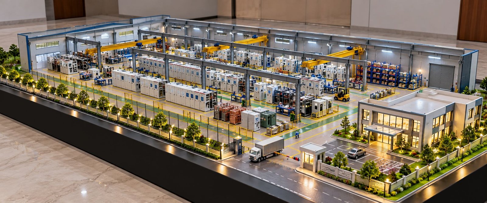
Smart Retaining Wall Monitoring Model for Civil Engineering Projects
Introduction to Smart Retaining Wall Monitoring
Smart Retaining Wall Monitoring is an important part of modern civil and structural engineering. It helps engineers observe retaining wall movement, soil conditions, groundwater pressure, and structural changes. Therefore, a Smart Retaining Wall Monitoring Model demonstrates how sensors, drainage systems, and data acquisition equipment work together in a physical engineering setup.
Retaining walls support soil at different ground levels and play an important role in highways, railway corridors, hillside developments, bridge approaches, and industrial sites. However, soil pressure, heavy rainfall, groundwater changes, and ground settlement can affect their performance over time. Consequently, engineers use suitable monitoring systems to collect information about structural and geotechnical conditions.
A physical retaining wall monitoring model presents these systems in a detailed three-dimensional format. It can include a concrete retaining wall, exposed soil layers, drainage pipes, inclinometers, piezometers, strain gauges, tilt sensors, crack meters, displacement sensors, and a data logger cabinet.
Moreover, the model helps viewers understand how different monitoring instruments relate to the structure and surrounding ground. For example, a piezometer measures groundwater pressure, while a tilt sensor measures angular orientation. Together, these details make the model useful for engineering presentations, technical training, infrastructure projects, and exhibitions.
At PAL Design Models, physical engineering models can be planned around project drawings, component references, site layouts, and presentation requirements. As a result, a customised model can communicate complex civil engineering concepts in a clear and professional way.
What Is a Smart Retaining Wall Monitoring Model?
A Smart Retaining Wall Monitoring Model is a physical scale representation of a retaining wall equipped with structural and geotechnical monitoring instruments. It demonstrates how engineers monitor selected changes in the wall, surrounding soil, and groundwater conditions.
A typical monitoring arrangement combines sensors, connecting cables, data acquisition equipment, and communication devices. Depending on the project, these systems may measure wall inclination, displacement, structural strain, crack movement, or groundwater pressure.
Additionally, the physical model can show how the retaining wall connects with its foundation, drainage arrangement, road surface, and surrounding terrain. This makes it easier for engineers, consultants, clients, and students to understand the overall engineering concept.
Purpose of Smart Retaining Wall Monitoring
The main purpose of retaining wall monitoring is to collect measurements that help engineers evaluate structural behaviour and investigate significant changes.
For example, engineers may use an inclinometer to investigate subsurface ground movement. Similarly, a crack meter can track changes in crack width, while a strain gauge measures local strain at a selected structural location.
A detailed retaining wall monitoring model can demonstrate:
- Retaining wall geometry and structural arrangement.
- Soil layers and ground profiles.
- Groundwater monitoring instruments.
- Drainage pipes and water outlets.
- Wall inclination and displacement sensors.
- Strain gauges and crack monitoring devices.
- Data loggers and communication equipment.
- Roadways, barriers, and surrounding infrastructure.
Physical Model and Digital Monitoring Systems
Digital monitoring systems collect and display sensor readings. In contrast, a physical scale model shows the locations of the instruments and their relationship with the retaining wall.
Furthermore, the model can complement CAD drawings, structural calculations, geotechnical reports, and digital dashboards. However, it does not replace professional engineering assessments or prove that an actual retaining wall is safe.
Key Components of Smart Retaining Wall Monitoring
A professional retaining wall monitoring model should represent the structural components and monitoring instruments relevant to the selected project. The exact arrangement depends on the wall design, site conditions, instrumentation plan, and presentation objectives.
Retaining Wall Structure
The retaining wall forms the central feature of the model. It represents the structure that holds back soil and supports changes in ground elevation.
Depending on the project, the model may represent a reinforced concrete retaining wall, gravity retaining wall, cantilever retaining wall, or mechanically stabilised earth wall.
Wall Face and Structural Detailing
A realistic model can include concrete textures, construction joints, wall segments, coping, foundation details, and selected structural supports.
For example, a reinforced concrete wall may feature a textured surface with visible panel joints. In addition, miniature mounting brackets can indicate the positions of selected monitoring instruments.
The model should follow the intended wall design rather than combine unrelated structural features. Consequently, the finished display will provide a more accurate representation of the engineering concept.
Soil Profile and Retained Earth
The soil behind the retaining wall influences the forces acting on the structure. Soil type, moisture content, compaction, and ground movement can affect its behaviour.
Therefore, a detailed model can use different colours and textures to represent selected soil layers.
Soil Layer Representation
The model may include topsoil, compacted fill, granular drainage material, and the underlying ground profile. A cutaway section can reveal the relationship between the retaining wall, foundation, drainage layer, and buried monitoring instruments.
Moreover, this arrangement makes the model useful for geotechnical engineering demonstrations and civil engineering education.
Inclinometer Monitoring System
An inclinometer helps engineers investigate subsurface ground movement along a borehole. In suitable applications, it can provide information about movement behind or near a retaining wall.
The physical model can represent an inclinometer through a vertical monitoring casing embedded within the soil section.
Inclinometer Installation Details
The miniature installation may include a borehole casing, a protective head assembly, a marked monitoring location, and a labelled connection to the monitoring system.
Additionally, the soil cutaway can reveal how the casing extends below ground level. This feature helps viewers understand the instrument’s location and purpose.
An inclinometer differs from a tilt sensor mounted directly on a wall. Therefore, the model should identify these instruments separately.
Piezometer and Groundwater Monitoring
A piezometer measures groundwater pressure or hydraulic head, depending on the instrument type and installation. Groundwater conditions matter because water pressure can affect the forces acting on a retaining structure.
A detailed model can show a piezometer inside the retained soil, with its monitoring point connected conceptually to a data acquisition system.
Groundwater and Drainage Representation
The model may include a groundwater level marker, a miniature monitoring installation, a drainage layer, and outlet pipes.
Furthermore, the soil cutaway can show the relative positions of the piezometer and the retaining wall. As a result, viewers can understand how groundwater monitoring relates to the surrounding ground.
Engineers should determine the actual installation depth and instrument type from the geotechnical investigation and monitoring requirements.
Strain Gauge Monitoring System
A strain gauge measures local strain at the point where engineers install it. These measurements can help engineers investigate changes in structural response under defined conditions.
In a Smart Retaining Wall Monitoring Model, miniature strain gauges can appear at selected locations on the wall face or on representative structural components.
Sensor Mounting and Cable Routing
The model may include a small sensor body, mounting points, thin connecting wires, and a nearby junction box.
Additionally, clear labels can identify the sensor location and the structural element under observation. These details help viewers understand the relationship between sensor placement and structural behaviour.
Tilt Sensor and Wall Inclination Monitoring
A tilt sensor measures angular orientation relative to a reference. When installed appropriately, it can help engineers monitor changes in a wall’s inclination over time.
The model can feature compact sensor housings mounted on selected areas of the retaining wall.
Tilt Sensor Installation
Miniature brackets, protective enclosures, and connecting wires can improve the realism of the installation.
Moreover, the sensor can connect visually to a nearby data logger cabinet. This arrangement illustrates how the monitoring equipment links to the data collection system.
Crack Meter and Crack Movement Monitoring
A crack meter tracks changes in crack width or relative movement across a selected surface. Engineers may use it to investigate crack progression or structural movement.
The physical model can include a clearly visible crack on a representative section of the retaining wall.
Crack Meter Detailing
The miniature instrument may feature two attachment points across the crack, a sensor body, and a measurement indicator or connecting cable.
Additionally, a small label can identify the monitoring location. This helps explain the monitoring concept during technical presentations.
However, the presence of a crack in the model does not mean that every retaining wall requires a crack meter.
Displacement Sensor
A displacement sensor measures movement between a reference point and a monitored component. Depending on the application, it may measure movement at a wall face, joint, or selected structural location.
A detailed model can represent these sensors through compact housings, mounting brackets, reference points, and connecting cables.
Furthermore, separate labels can distinguish wall displacement monitoring from subsurface ground movement monitoring. Consequently, viewers can identify the purpose of each instrument more easily.
Data Logger and Monitoring Cabinet
A data logger collects information from compatible monitoring instruments and stores or transmits the measurements according to the system configuration.
The physical model can represent the data logger as a small control cabinet, monitoring enclosure, or miniature instrument station.
Data Acquisition and Communication
The monitoring section may include:
- A data acquisition unit.
- Sensor connection terminals.
- A communication gateway.
- A power supply or battery enclosure.
- An antenna or communication device.
- A monitoring display or control interface.
Depending on the project, a small solar panel can represent an independent power source for selected remote monitoring equipment.
However, the actual power supply and communication arrangement should follow the intended system design. In addition, clear equipment labels can make the monitoring section easier to understand.
Smart Retaining Wall Monitoring and Drainage Systems
Drainage plays an important role in retaining wall engineering because water accumulation behind a wall can increase hydrostatic pressure. Therefore, the physical model should represent the intended drainage arrangement wherever it forms part of the project.
Drainage Layer and Filter Material
A typical drainage concept may include granular drainage material, suitable filter layers, and drainage pipes behind the wall.
The model can show a distinct granular layer between the retained soil and the wall. Different colours and textures help viewers distinguish the drainage section from other soil layers.
Drainage Pipes and Outlets
Miniature perforated pipes, collector drains, outlet pipes, and drainage channels can represent the water management system.
Additionally, the model may feature a visible outlet near the base or side of the retaining wall. As a result, viewers can follow the drainage arrangement through the physical display.
The actual outlet position and drainage design should follow the approved engineering requirements and site conditions.
Surface Water Management
Roadside drains, kerbs, channels, and surface water collection points can form part of the model when the surrounding infrastructure requires them.
Furthermore, these details demonstrate how engineers manage water around the roadway and retaining wall. Consequently, the model presents the wall as part of a complete site layout.
Roadway and Infrastructure Above the Retaining Wall
Retaining walls often support roads, parking areas, railway infrastructure, industrial access routes, and developed land. Therefore, the upper section of the model can show the infrastructure supported by the wall.
Road Surface and Vehicle Movement
A realistic model may include a miniature road with lane markings, barriers, streetlights, and small vehicles.
These features communicate the relationship between the retaining wall and the roadway. Moreover, miniature vehicles help establish the scale of the complete installation.
Road Safety Features
Depending on the reference design, the model may include crash barriers, guardrails, kerbs, pedestrian paths, and roadside drainage.
In addition, miniature road signs and streetlights can improve the presentation. However, the team should position these elements carefully so that they do not obscure the monitoring instruments.
Hillside Landscaping and Ground Profile
The model may show a sloping hillside with miniature vegetation, exposed soil layers, and ground contours.
This arrangement suits projects involving retaining walls along highways, elevated roads, hillside developments, and embankments.
Nevertheless, landscaping should remain secondary to the main engineering components. The retaining wall, monitoring sensors, soil profile, and drainage system should remain clearly visible.
How a Smart Retaining Wall Monitoring Model Is Made
Professional engineering model making involves several coordinated stages. Each stage helps the team represent the intended structure and monitoring concept accurately.
Project Drawing Review
The process begins with a review of retaining wall drawings, structural details, site layouts, geotechnical sections, sensor locations, and reference photographs.
The model-making team identifies the wall geometry, soil profile, monitoring equipment, drainage arrangement, surrounding infrastructure, and required level of detail.
Additionally, the team confirms missing information before fabrication begins. This reduces confusion and helps the team follow the intended design.
Scale Selection and Baseboard Planning
The scale depends on the actual wall dimensions, available display space, required sensor details, and presentation purpose.
A long retaining wall often suits a wide, low-profile rectangular baseboard. This format provides enough length to display the wall, soil cutaway, monitoring instruments, road infrastructure, and drainage system without making the model unnecessarily tall.
Moreover, a wide layout provides room for labels and miniature equipment. The team must maintain consistent proportions while keeping the sensors visible.
CAD Design and Component Preparation
CAD drawings and three-dimensional references can help the team prepare the base layout and individual components.
For example, the team can fabricate the retaining wall, sensor housings, data logger cabinet, road barriers, and drainage components separately.
Furthermore, three-dimensional modelling helps identify potential layout conflicts before physical assembly begins. As a result, the team can plan component placement more accurately.
Fabrication of the Retaining Wall
The model-making team can use PVC sheets, acrylic, resin, and other suitable materials to fabricate the wall.
Depending on the required finish, the surface may feature miniature concrete textures, panel joints, support elements, and selected structural details.
The objective is to create a realistic physical representation of the intended wall design. In addition, a consistent finish helps the monitoring instruments stand out against the wall surface.
Soil Cutaway and Terrain Formation
The team can create the ground profile using lightweight modelling materials, carved foam, textured compounds, and suitable surface finishes.
Different colours and textures can distinguish topsoil, compacted earth, granular drainage material, and other represented ground layers.
In addition, a cutaway section can reveal buried instruments and drainage components. This feature makes the model particularly useful for explaining subsurface monitoring.
Sensor Fabrication and Installation
Miniature sensors can use small enclosures, plastic components, metal details, wires, mounting brackets, and printed labels.
The team then positions each sensor according to the reference layout.
For example, the model may show a piezometer within the soil, an inclinometer casing in a borehole, a strain gauge on the wall, and a crack meter across a representative crack.
The team should identify each instrument accurately because the monitoring methods are not interchangeable. Therefore, sensor placement and labelling deserve careful attention during assembly.
Cable Routing and Data Logger Assembly
Thin wires can represent sensor cables and communication connections.
These wires may follow the wall face, pass through small cable supports, or lead toward a junction box and data logger cabinet.
Furthermore, neatly arranged wiring improves realism and visual clarity. It also helps viewers follow the connection between the sensors and the data collection area.
If the project requires a working demonstration, the team can incorporate compatible sensors and a controller. However, an illustrative model does not need functional electronics unless the client requests them.
Road, Drainage and Landscaping Details
The team adds the road surface, barriers, miniature vehicles, drainage channels, outlet pipes, vegetation, and access routes according to the approved layout.
Additionally, small streetlights and a monitoring station can improve the overall presentation.
The components should remain balanced so that the monitoring technology and retaining wall remain the main focus. Consequently, the finished model can communicate the engineering concept without unnecessary visual clutter.
Painting, Labelling and Final Assembly
The finishing stage includes surface painting, colour coordination, equipment identification, and final assembly.
Clear labels can identify the inclinometer, piezometer, strain gauge, tilt sensor, crack meter, displacement sensor, drainage system, and data logger.
Finally, the team checks alignment, component visibility, finishing quality, and the overall presentation from different viewing angles.
Materials Used for Smart Retaining Wall Models
The choice of materials depends on the scale, required finish, durability, component complexity, and display environment.
PVC Sheets and Acrylic
PVC sheets and acrylic are suitable for wall sections, instrument enclosures, base details, monitoring cabinets, and selected structural elements.
Moreover, these materials can be cut and assembled to create clean edges and consistent dimensions.
Foam and Terrain Modelling Materials
Lightweight foam and suitable modelling compounds can represent the soil profile, slopes, and terrain contours.
Textured finishes help distinguish different ground materials without adding unnecessary weight. Additionally, these materials allow the team to create a visible cutaway section.
3D Printing and Laser Cutting
3D printing is useful for small sensor housings, monitoring cabinets, mounting brackets, and specialised components.
Similarly, laser cutting can produce wall panels, baseboard elements, labels, and selected structural details with consistent dimensions.
Wires, Miniature Pipes and Electronic Components
Fine wires can represent sensor connections, while miniature pipes and fittings can demonstrate drainage and cable routing.
If functional monitoring is required, the team can incorporate compatible electronic sensors, a microcontroller, a data logger, or a display according to the project’s needs. Therefore, material and component selection should reflect the intended purpose of the model.
Applications of Smart Retaining Wall Monitoring Models
A detailed physical model can support technical communication across several civil engineering and infrastructure applications.
Civil Engineering Colleges and Universities
Educational institutions can use the model to explain retaining wall behaviour, geotechnical instrumentation, structural monitoring, and drainage concepts.
Moreover, labelled components help students connect theoretical concepts with physical installations. For example, the soil cutaway can demonstrate the placement of subsurface monitoring equipment.
Infrastructure and Highway Projects
Highway contractors and infrastructure consultants may use the model to present retaining walls along elevated roads, embankments, and hillside routes.
The physical model can illustrate sensor locations, drainage arrangements, and surrounding road infrastructure. In addition, it can support discussions about the relationship between the retaining wall and the supported roadway.
Geotechnical and Structural Engineering Consultancies
Engineering consultancies can use the model to explain proposed monitoring arrangements during technical presentations.
Additionally, it can support discussions about instrumentation placement, data collection, and monitoring objectives. Consequently, clients can understand the proposed monitoring concept more easily.
Construction Companies and Project Developers
Construction companies may use a physical scale model to communicate the intended arrangement of retaining structures and associated infrastructure.
However, final construction decisions must rely on approved engineering documents and site-specific assessments.
Engineering Exhibitions and Technical Demonstrations
A detailed retaining wall monitoring model can serve as a display for engineering exhibitions, infrastructure conferences, and technical demonstrations.
Furthermore, a wide, low-height presentation format allows viewers to observe the wall face, terrain, and monitoring equipment together. This arrangement also suits landscape-oriented feature images and exhibition displays.
Benefits of a Custom Engineering Scale Model
Clear Technical Communication
A physical model brings the retaining wall, soil profile, sensors, drainage, and monitoring cabinet into one visual presentation. Consequently, viewers can understand the overall system more easily.
Improved Understanding of Sensor Placement
The model shows where different instruments may be installed and which structural or geotechnical parameters they monitor.
For example, a piezometer can appear within the soil, while a tilt sensor can sit on the wall. This visual distinction helps explain the purpose of each instrument.
Better Project Presentation
A professionally finished model can support presentations to clients, project managers, consultants, and educational audiences.
In addition, detailed labels and miniature infrastructure can make the demonstration easier to follow.
Customisation for Different Projects
Retaining walls differ in geometry, construction method, ground conditions, and monitoring requirements. Therefore, a custom model can represent the selected wall type and instrumentation plan.
Physical and Working Demonstration Options
A model can serve as a static physical display or incorporate selected working components.
For example, a working version may use tilt sensors or displacement sensors connected to a controller and display. Nevertheless, the demonstration should clearly distinguish simulated readings from validated structural monitoring results.
Choosing a Professional Engineering Model Making Company
Selecting an experienced model maker is important when the project involves structural details, geotechnical instruments, drainage arrangements, and miniature electronic components.
Engineering Drawing Interpretation
The company should be able to interpret retaining wall drawings, site layouts, sensor arrangements, and relevant technical references.
Precision Fabrication
Review examples of physical engineering models that include detailed structures, equipment, terrain, and miniature infrastructure.
Furthermore, photographs from multiple angles can help assess the quality of fabrication and finishing.
Sensor and Component Detailing
Confirm whether the model maker can represent the required monitoring instruments, connecting wires, data logger cabinet, drainage elements, and identification labels.
Custom Baseboard and Presentation
A wide rectangular baseboard can accommodate a long retaining wall and surrounding infrastructure. Additionally, a protective acrylic or glass enclosure may be included for long-term display.
Project Coordination
Before fabrication begins, confirm the scale, dimensions, materials, reference drawings, component list, display requirements, and delivery schedule.
Consequently, the final model can match the intended presentation objectives more closely.
Smart Retaining Wall Monitoring Model Making by PAL Design Models
PAL Design Models provides physical scale model making for architectural, industrial, engineering, and specialised project presentation requirements.
For a Smart Retaining Wall Monitoring Model, the team can develop a customised design using available structural drawings, geotechnical sections, sensor locations, site layouts, and presentation requirements.
Depending on the approved design, the model may include a retaining wall, exposed soil profile, inclinometer casing, piezometer, strain gauges, tilt sensors, crack meters, displacement sensors, drainage pipes, a road surface, miniature vehicles, and a data logger station.
Additionally, the presentation can incorporate realistic textures, detailed cable routing, equipment labels, miniature landscaping, streetlights, and a finished rectangular baseboard.
Where required, selected electronic components can demonstrate sensor readings or basic monitoring functions. However, the scope of a working model should be agreed upon before fabrication begins.
For more information about custom engineering and industrial scale models, visit https://paldesignmodels.com.
Frequently Asked Questions
What is a Smart Retaining Wall Monitoring Model?
A Smart Retaining Wall Monitoring Model is a physical scale model that demonstrates how structural and geotechnical instruments can monitor selected aspects of retaining wall behaviour. It may include sensors, drainage components, soil layers, and data acquisition equipment.
Which sensors can be included in the model?
Depending on the project, the model may include an inclinometer, piezometer, strain gauge, tilt sensor, crack meter, displacement sensor, and data logger. Each instrument serves a different monitoring purpose.
Can the retaining wall model be made as a working model?
Yes. A working version can incorporate selected electronic sensors, a controller, and a display to demonstrate basic measurement and data collection. However, the demonstration does not automatically provide validated information about a real retaining wall’s safety.
Which materials are suitable for this engineering model?
PVC sheets, acrylic, foam, resin, miniature wires, plastic pipes, and 3D-printed components may be used. The final material selection depends on the scale, required finish, and complexity of the model.
Can the model include a road and drainage system?
Yes. A customised model can include a road above the wall, miniature vehicles, safety barriers, surface drains, drainage outlets, and terrain details according to the reference design.
Who can use a retaining wall monitoring scale model?
Civil engineering colleges, geotechnical consultants, structural engineers, infrastructure contractors, highway project teams, and engineering exhibition organisers may use the model for technical communication and demonstrations.
What is the difference between an inclinometer and a tilt sensor?
An inclinometer installation commonly measures subsurface movement along a borehole, while a tilt sensor measures angular orientation at its installation point. Their selection depends on the monitoring objective and engineering requirements.
Can a physical model replace structural monitoring equipment?
No. A physical model illustrates the monitoring concept. Actual structural monitoring requires suitable instruments, correct installation, calibrated measurements, data interpretation, and assessment by qualified professionals.
Final Thoughts
A Smart Retaining Wall Monitoring Model combines civil engineering structures, geotechnical instrumentation, drainage design, and modern monitoring technology in one detailed physical presentation.
From the retaining wall and soil profile to the inclinometer, piezometer, strain gauge, tilt sensor, crack meter, displacement sensor, and data logger, each component helps explain a different aspect of the monitoring arrangement.
Moreover, a carefully designed model can demonstrate how monitoring equipment relates to the surrounding infrastructure and how engineers collect information about structural and ground behaviour.
For engineering consultants, civil engineering institutions, infrastructure contractors, and project developers, a customised physical scale model can complement drawings, technical reports, and digital presentations. With accurate proportions, realistic materials, detailed sensor installations, clear labelling, and professional finishing, the model becomes a practical tool for engineering communication.
PAL Design Models can develop a customised retaining wall monitoring model based on the project’s available drawings, component requirements, and presentation objectives. Ultimately, the goal is to create a realistic and well-detailed physical model that presents the engineering concept clearly and professionally.