Manufacturing Plant Models for Project Visualization
A manufacturing plant is much more than a large factory building. It is a complete industrial environment that can include production halls, warehouses, process equipment, storage tanks, pipe racks, loading areas, internal roads, parking, offices, security gates, landscaping, and service facilities. When a project contains all these elements, a Manufacturing Plant Model can present the complete development in one clear physical view.
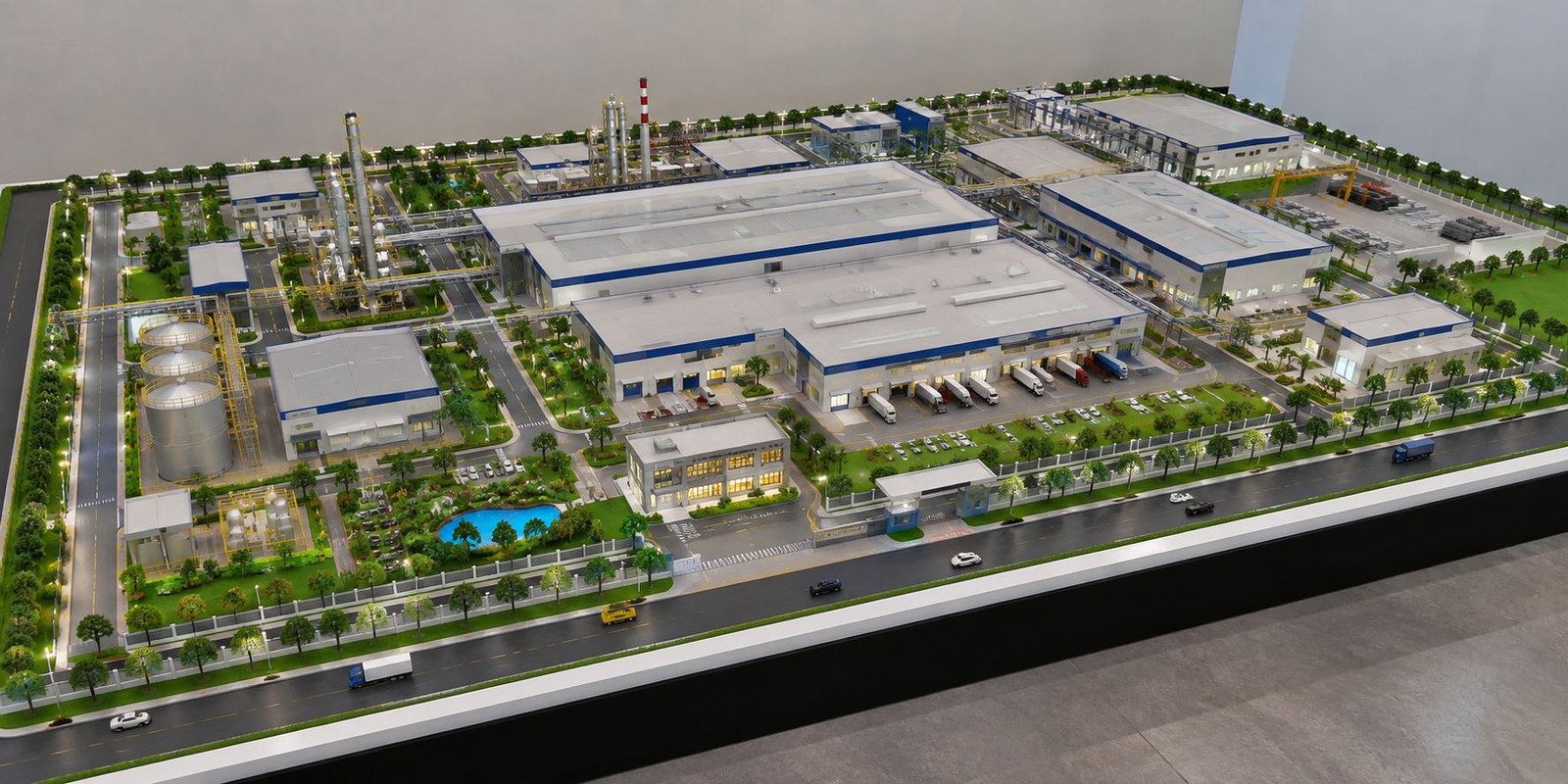
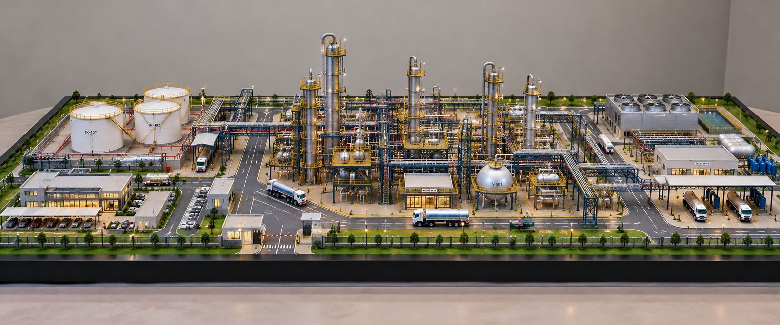
The model shown in this project follows a wide physical layout. Its overall length and width are much greater than its height. This low-height and wide arrangement works particularly well for industrial projects because manufacturing plants usually occupy large sites with several low-rise buildings. Therefore, the model focuses on the complete industrial layout rather than only the height of individual buildings.
A detailed physical model also helps viewers understand how different parts of a manufacturing facility work together. Instead of looking at separate drawings, clients and project teams can see production areas, warehouses, roads, equipment, parking, landscaping, and supporting facilities together.
What Is a Manufacturing Plant Model?
A Manufacturing Plant Model is a scaled physical representation of an industrial facility and its surrounding site. It can show the main production buildings, warehouses, process units, storage facilities, offices, roads, parking, loading areas, landscaping, vehicles, and other supporting infrastructure.
A conventional architectural model may focus mainly on one building. In contrast, a manufacturing plant model can represent an entire industrial campus. This makes it useful for explaining how different buildings, departments, roads, equipment, and supporting facilities connect within the same site.
Moreover, the purpose of the model goes beyond showing the exterior of a factory. A detailed model can communicate site planning, circulation, equipment placement, logistics, storage, production areas, and the relationship between different functional zones.
As a result, the physical model becomes more than a presentation object. It becomes a visual representation of the complete industrial environment.
Wide and Low-Height Physical Model Design
One of the main characteristics of this manufacturing plant model is its wide rectangular composition. The baseboard extends significantly in length and width, while the major factory buildings remain comparatively low in height.
This proportion allows viewers to see a larger portion of the industrial campus from an elevated viewpoint. The main factory, warehouses, process areas, roads, parking, landscaping, and other facilities appear together within one physical model.
Furthermore, a wide-format model works particularly well for large industrial developments. Increasing building height does not always communicate the actual scale of an industrial project. Instead, the site area and horizontal circulation often provide more important information.
Therefore, the wide baseboard creates enough space to show the relationship between production areas, storage areas, transportation routes, offices, warehouses, and supporting facilities.
Main Manufacturing Building
The central portion of the model contains a large manufacturing building. Its broad footprint and low industrial profile immediately establish the main production area of the project.
The building has a large roof surface with detailed roof elements and service components. In addition, multiple access and loading points appear along the front side. These areas help explain the connection between the manufacturing building and the surrounding vehicle circulation.
The main manufacturing building acts as the central element of the industrial campus. Around it, smaller buildings, warehouses, process facilities, roads, parking areas, and landscaped spaces create a complete industrial environment.
Consequently, viewers can quickly identify the main production facility and then understand how the supporting areas connect with it.
Production and Manufacturing Areas
Large industrial buildings represent the production and manufacturing areas of the project. Their size, shape, and broad floor areas communicate their industrial purpose.
In a real manufacturing facility, production spaces can contain machinery, assembly lines, equipment, storage systems, and material-handling facilities. However, a physical model does not always need to show every internal component. Instead, the model can communicate these functions through building forms, loading areas, connected structures, and surrounding circulation.
Furthermore, the position of each production building matters. The buildings need logical connections with warehouses, process areas, storage facilities, and transportation routes.
For this reason, a detailed physical model provides a useful overview. Viewers can understand the relationship between several functional areas without studying each drawing separately.
Secondary Industrial Buildings
In addition to the main factory, several smaller industrial buildings surround the manufacturing facility. These structures add depth and realism to the industrial campus.
Depending on the project, these buildings can represent workshops, assembly areas, maintenance facilities, technical departments, service buildings, production support areas, or additional manufacturing units.
Moreover, their different sizes and locations create a functional hierarchy across the site.
Rather than showing one large factory in isolation, the model presents multiple structures working together. As a result, the viewer gets a more complete understanding of the industrial development.
Warehouse Buildings
Warehouses form another major part of the manufacturing plant model. Several large warehouse-type buildings appear around the industrial campus.
Their broad footprints and large roof spans distinguish them from smaller office and service buildings.
Warehouses can support the storage of raw materials, components, packaging materials, finished products, or other industrial goods. The exact purpose depends on the individual project.
Furthermore, warehouse placement plays an important role in manufacturing planning. A warehouse needs a practical connection with production areas and transportation routes.
Therefore, showing warehouses in the physical model helps viewers understand the relationship between storage, production, roads, and loading facilities.
Warehouse Loading and Dispatch Areas
The warehouse buildings connect with dedicated vehicle-access and loading areas. These spaces create a clear relationship between storage buildings and transportation.
Multiple miniature trucks appear around the industrial buildings. Besides adding realism, these vehicles provide a useful sense of scale.
For example, a viewer can immediately understand the approximate size of a warehouse by comparing it with the trucks positioned near its loading areas.
Furthermore, the loading zones show how vehicles can approach the warehouses for receiving and dispatch operations.
Therefore, these areas are not simply decorative details. They communicate the connection between warehouses, internal roads, transportation, and industrial logistics.
Process Equipment Area
The process equipment area adds significant engineering detail to the manufacturing plant model.
This section contains tall vertical structures, process towers, cylindrical components, pipework, platforms, and support structures. These elements create a strong visual contrast with the low-rise manufacturing and warehouse buildings.
Moreover, the process area gives the model a technical engineering character. It shows that the industrial campus contains outdoor process equipment in addition to enclosed buildings.
Tall structures also create visual variation across the wide site. Therefore, they help viewers identify the process section quickly while adding depth and height to the overall model.
Storage Tanks
Several cylindrical storage tanks appear within the industrial area.
Their circular forms create a strong contrast with the rectangular factory and warehouse buildings. In a detailed engineering model, these tanks can include cylindrical bodies, top sections, support structures, platforms, ladders, and connected piping.
Furthermore, their position helps explain the relationship between storage areas and process equipment.
Although storage tanks occupy a smaller part of the complete model, they add significant technical detail. As a result, they help the model communicate the engineering character of the industrial facility.
Pipe Racks and Industrial Piping
Pipe racks and industrial piping form another important part of the manufacturing plant model.
The process area includes elevated pipework supported by structural frames. These systems visually connect different parts of the industrial facility.
A professional engineering model can represent horizontal pipelines, vertical connections, pipe racks, support structures, platforms, and equipment connections.
Moreover, these details help viewers understand that an industrial plant contains interconnected systems. Different buildings and process areas do not operate as completely separate units.
The pipe racks also add depth because they create multiple levels between the ground surface and taller process equipment.
Internal Roads and Circulation
Internal roads connect the different areas of the manufacturing campus.
They provide access to the main factory, warehouses, process areas, parking spaces, entrance facilities, and loading zones.
A broad road runs along the front edge of the model. In addition, several internal roads branch toward individual buildings.
This arrangement helps explain how vehicles can move between different functional areas.
Furthermore, circulation plays an important role in a manufacturing facility. Employees, visitors, delivery vehicles, service vehicles, and trucks may follow different routes.
Therefore, a physical model makes these circulation relationships much easier to understand from a single viewpoint.
Trucks and Miniature Vehicles
Miniature trucks and cars appear throughout the model.
These vehicles perform an important visual function. First, they establish the scale of the buildings and roads. Second, they communicate the operational character of the industrial site.
Trucks appear near warehouse and loading areas, while cars appear around parking spaces and office buildings.
Because viewers recognize the approximate size of cars and trucks, these small elements make the overall model easier to understand.
Additionally, vehicles prevent the industrial site from looking empty. Instead, they create a sense of movement and activity across the campus.
Administrative and Office Building
A smaller glazed building appears toward the front section of the industrial campus.
Compared with the large production buildings, this structure has a more compact and refined appearance. Depending on the project, it can represent an administrative office, reception building, management facility, visitor center, or corporate office.
Its location near the main road creates a clear distinction between public-facing and industrial areas.
Furthermore, visitors and administrative staff may use this part of the site differently from production and logistics teams.
As a result, the building contributes to the functional organization of the overall industrial campus.
Parking Areas
Parking areas form an important part of the site layout.
The model includes miniature cars within designated parking spaces. These areas can represent employee and visitor parking.
Furthermore, parking helps explain how people access the manufacturing facility.
When viewers see parking together with roads, offices, entrance areas, and production buildings, they can understand the movement pattern across the site more easily.
Therefore, parking is not simply an additional site detail. It also helps communicate the relationship between people, buildings, and circulation.
Entrance and Security Gate
The front portion of the model contains the main entrance and security area.
The entrance connects the internal industrial campus with the external road network. In addition, the gate creates a clear transition between the public road and the controlled industrial facility.
The entrance area can represent security checking, visitor access, vehicle control, and controlled movement into the manufacturing campus.
Moreover, small details can significantly improve the realism of this area. These details can include gates, guard rooms, road markings, entrance paving, and landscaping.
Together, these features create a clear and professional entrance presentation.
Boundary and Perimeter Planning
The complete industrial development sits within a defined rectangular boundary.
This boundary establishes the overall project footprint and gives the model a clear edge.
Trees and landscaping appear along sections of the perimeter. These green areas create a visual buffer between the industrial facility and its surroundings.
Furthermore, the perimeter helps viewers understand that the factories, warehouses, process areas, roads, and service buildings form one integrated industrial development.
Landscaping and Green Areas
Although the project focuses on manufacturing, landscaping still plays an important role.
Trees appear along roads, around buildings, near parking areas, and along the perimeter.
In addition, green spaces visually separate different buildings and open areas. This makes the industrial campus look more organized.
The model includes grass areas, planted spaces, trees, and landscaped zones around important parts of the site.
These elements create a clear visual difference between buildings, roads, and open spaces. Therefore, landscaping contributes to both realism and presentation quality.
Manufacturing Plant Model With Detailed Site Planning
The strength of this model comes from the combination of buildings and external infrastructure.
The main factory does not stand alone. Instead, warehouses, process equipment, storage tanks, roads, vehicles, parking, offices, and landscaping surround it.
Together, these elements create a complete representation of an industrial site.
The viewer can follow the project from the main entrance to the internal roads. From there, the viewer can understand the connection between production buildings, warehouses, process areas, storage facilities, and loading zones.
As a result, the model provides a systematic visual explanation of the complete manufacturing campus.
Importance of Scale in Manufacturing Plant Models
Scale selection plays an important role in professional model making.
A manufacturing project can cover a very large site. Therefore, an unnecessarily large model may become difficult to display and transport.
On the other hand, a very small model may hide important engineering details.
For this reason, the model maker must balance overall site dimensions with the required level of detail.
Important factors include building size, equipment dimensions, road width, vehicle size, landscaping, process equipment, viewing distance, and available display space.
The selected scale should keep the complete project visually clear. At the same time, it should preserve important architectural and engineering details.
Materials Used for Manufacturing Plant Models
Professional model makers can use different materials for different parts of an industrial model.
Materials for Major Buildings
Large factory and warehouse structures can use acrylic, PVC sheets, MDF, foam board, and other model-making materials.
These materials can create clean surfaces and accurate building forms.
Materials for Small Components
Smaller components may require acrylic rods, metal wires, transparent sheets, or specially fabricated parts.
These materials help create finer technical details.
3D Printing for Industrial Components
Furthermore, 3D printing can create detailed industrial equipment and custom components.
It works particularly well for complex shapes that require consistent dimensions and fine detailing.
Laser Cutting for Precise Components
Similarly, laser cutting can create precise building components, repetitive architectural elements, road patterns, panels, and other accurately dimensioned parts.
Therefore, the model maker can select materials and fabrication methods according to the scale, detail level, durability, and presentation requirements.
LED Lighting in Manufacturing Plant Models
LED lighting can enhance selected areas of a manufacturing plant model.
Lights can appear inside factory buildings, administrative offices, entrance structures, and other important areas.
Furthermore, carefully positioned lighting can improve the model during presentations and exhibitions.
It can also create a day-and-night presentation effect.
However, lighting should support the physical model rather than dominate it. The main objective should remain the clear presentation of the manufacturing facility and its site planning.
Manufacturing Plant Models for Client Presentation
Large industrial projects can be difficult to explain through drawings alone.
A physical model creates a common visual reference for architects, engineers, clients, consultants, and project managers.
Instead of discussing separate drawings for the factory, warehouses, roads, process areas, and parking, the team can view the complete project together.
For example, the presenter can point directly to the main production building, warehouse, process equipment, storage tanks, loading zones, parking, and entrance.
As a result, the model can make communication easier during meetings and project presentations.
Manufacturing Plant Models for Engineering Projects
Manufacturing plant models can support many types of industrial projects.
Engineering companies, EPC contractors, industrial consultants, developers, architects, and project management teams can use these models for presentations and project communication.
Moreover, a physical model can combine architectural and engineering information within one representation.
For example, the building envelope can appear together with process equipment, pipe racks, storage tanks, roads, loading areas, and supporting facilities.
Therefore, different project teams can understand the same industrial environment from a shared perspective.
Professional Manufacturing Plant Model Making
Professional model making begins with project information. The model maker studies architectural drawings, site plans, elevations, engineering layouts, equipment details, and other available project information.
Next, the team selects a suitable scale according to the site dimensions and required level of detailing.
A strong rectangular baseboard then provides the foundation for the complete site. Since this project has a wide layout, the baseboard provides sufficient space for the major components.
The main factory, warehouses, offices, and supporting buildings follow the selected scale. After that, the model maker adds storage tanks, process towers, pipe racks, platforms, and other industrial components.
Meanwhile, internal roads, parking areas, loading zones, and vehicle circulation connect the complete site.
The team then adds trees, grass, shrubs, green areas, and perimeter landscaping around the buildings and roads.
Cars and trucks provide scale and communicate industrial movement. In addition, the team can integrate LED lighting into selected buildings and presentation areas when required.
Finally, the completed model undergoes a detailed quality check. The team checks alignment, proportions, cleanliness, equipment placement, road connections, landscaping, lighting, and overall presentation quality.
Why Physical Manufacturing Plant Models Are Valuable
The main advantage of a physical manufacturing plant model is its ability to bring the entire project into one visible environment.
The viewer does not need to mentally combine several drawings.
Instead, production buildings, warehouses, process equipment, storage tanks, roads, parking areas, vehicles, landscaping, and entrance facilities appear together.
Furthermore, this approach helps people who may not regularly work with technical drawings.
Clients can view the project from different angles. Project teams can also discuss individual areas while seeing their relationship with the rest of the industrial campus.
As a result, the physical model becomes a useful communication tool for project meetings, presentations, exhibitions, and design discussions.
Conclusion
The Manufacturing Plant Model for Project Visualization represents an entire industrial development through a detailed physical scale model.
The model combines the main manufacturing building with warehouses, secondary industrial buildings, process equipment, storage tanks, pipe racks, internal roads, loading areas, trucks, parking, administrative facilities, security areas, boundary planning, and landscaping.
Its wide and relatively low-height design works particularly well for large manufacturing projects. It provides a clear view of the complete site while maintaining the visual proportions of a real industrial campus.
Moreover, the model demonstrates that professional engineering and architectural model making involves much more than reproducing the exterior of a factory.
A detailed manufacturing plant model can communicate production, storage, logistics, engineering infrastructure, transportation, administration, and site planning together.
For industrial companies, EPC contractors, architects, engineers, developers, project managers, and consultants, such a model can support project visualization, client presentations, design discussions, technical communication, and exhibition displays.
Ultimately, a well-designed manufacturing plant model transforms a complex industrial layout into a physical environment that viewers can understand from multiple angles.
It brings architecture, engineering, and industrial planning together in one detailed presentation. Therefore, it provides a practical way to visualize the complete manufacturing project before the real facility reaches the construction stage.