Wind Farm Development Scale Model for Renewable Energy Projects
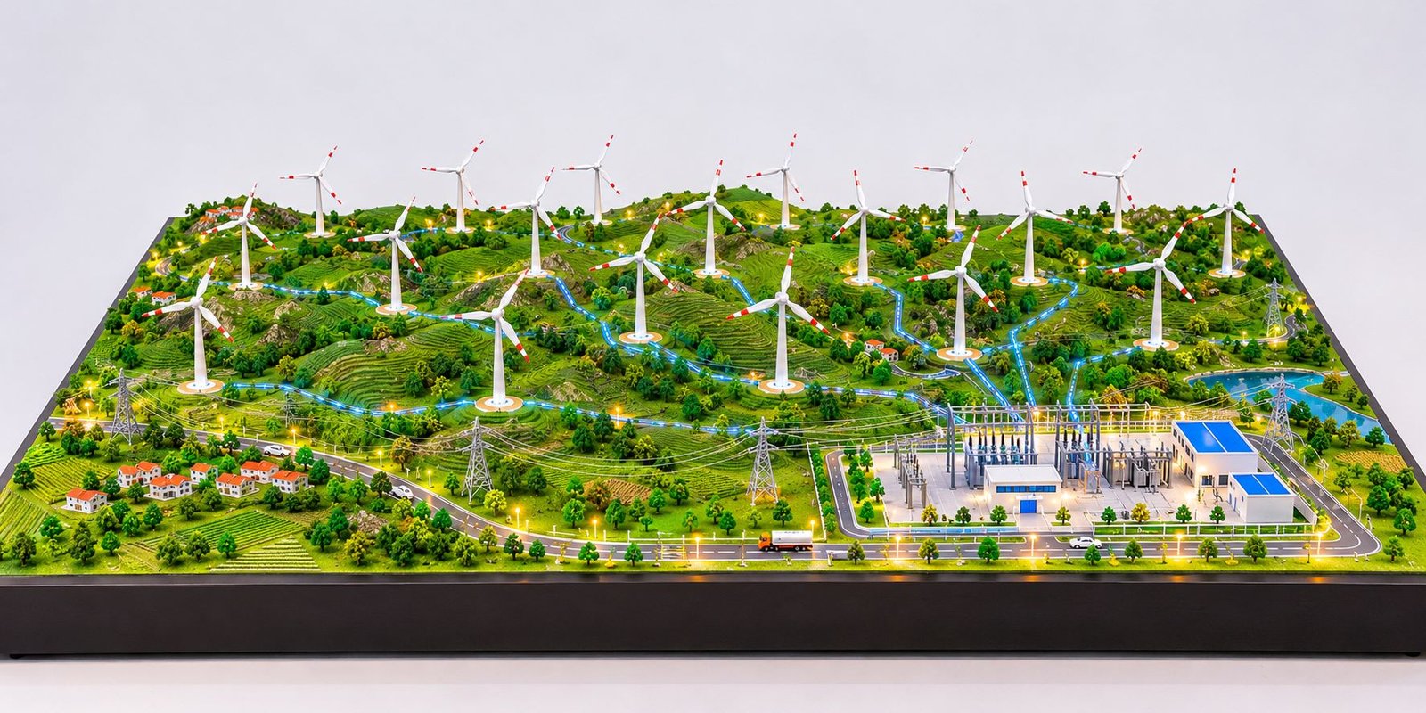
A Wind Farm Development Scale Model helps renewable energy companies present large wind power projects through a detailed three-dimensional physical display. It brings wind turbines, electrical infrastructure, access roads, substations, terrain features and surrounding developments together on one carefully designed baseboard. As renewable energy projects continue to expand, developers need effective ways to explain their layouts, infrastructure planning and technical features. A professional physical model makes these complex developments easier to understand.
A wind farm involves much more than installing turbines across an open area. Project developers must consider land conditions, turbine locations, access roads, electrical connections, power evacuation systems and supporting facilities. Each component plays an important role in the overall development. Therefore, a detailed scale model can help project teams communicate the complete arrangement through a clear visual presentation.
At PAL Design Models, we focus on converting engineering drawings, site layouts, technical references and project information into detailed physical models. Our approach combines careful planning, suitable materials and precise fabrication techniques. As a result, clients can present their wind energy projects through realistic miniature structures and clearly visible infrastructure.
Understanding a Wind Farm Development Scale Model
A Wind Farm Development Scale Model represents a planned or existing wind energy project in miniature form. It displays the main project components according to a selected scale and helps viewers understand the complete site arrangement.
A typical model includes multiple wind turbines distributed across a defined geographical area. In addition, it can show internal roads, electrical cable routes, transmission towers, pooling substations, nearby settlements and natural landscape features. Depending on the project requirements, the model can represent a small wind energy installation or a large wind farm covering an extensive area.
The main purpose of this model is to explain the project layout in a simple and visual format. For example, a developer may need to show the distance between turbines, the position of the pooling substation and the route of electrical connections. A physical model brings these details together and allows viewers to understand their relationship.
Unlike a simple illustration, a professionally manufactured model uses real materials and physical miniature components. Model makers can combine acrylic, polystyrene, PVC, MDF, plywood and 3D-printed parts to create different structures. Furthermore, they can add miniature vehicles, trees, buildings, road markings and electrical equipment to improve the presentation.
The final design depends on the project drawings, selected scale, display dimensions and required level of detailing.
Importance of Physical Wind Farm Models in Renewable Energy Projects
Renewable energy developments contain several technical and geographical elements. Engineering drawings communicate accurate information; however, some viewers may find it difficult to understand the complete project through two-dimensional plans alone.
A physical wind farm model provides a three-dimensional view of the development. Consequently, project teams can explain the layout from different viewing angles and highlight important infrastructure during meetings and presentations.
Clear Presentation of Wind Turbine Locations
Wind turbines usually occupy different positions across a large project area. Their arrangement depends on the approved site layout, available land, terrain conditions and engineering requirements.
A scale model displays every turbine in relation to the surrounding structures. Therefore, viewers can understand the overall turbine arrangement without studying several separate drawings.
Moreover, the model can show the orientation of turbine blades, tower positions and nearby access routes. These details help project teams explain the proposed development more effectively.
Better Understanding of Site Infrastructure
A wind farm requires supporting infrastructure such as internal roads, electrical routes, substations, maintenance areas and transmission facilities. These components connect different sections of the project.
A physical model displays these facilities together. As a result, viewers can follow the overall infrastructure arrangement and understand how individual components support the wind energy project.
Effective Communication with Stakeholders
Project developers often present wind energy developments to investors, government departments, consultants, engineering teams and other stakeholders. Each group may require a different level of technical information.
A detailed physical model gives the presentation a common visual reference. For instance, a presenter can point towards a turbine, substation or transmission route while explaining its purpose. This approach makes technical discussions easier to follow.
Improved Project Demonstration
A wind farm model can serve as a permanent display at a corporate office, project site, exhibition or visitor centre. In addition, companies can use it during renewable energy events and technical presentations.
An attractive physical display also helps visitors understand the project’s main features at a glance.
Major Components Included in a Wind Farm Scale Model
Every wind farm follows its own design and site requirements. Therefore, the components in a Wind Farm Development Scale Model depend on the drawings and information supplied by the client.
However, a detailed physical model can include several important elements.
Wind Turbine Structures
Wind turbines form the main visual feature of a wind energy project. Each turbine generally consists of a tower, nacelle, hub and rotor blades.
For a physical model, manufacturers can create these components using lightweight materials. For example, acrylic tubes or suitable plastic parts can represent turbine towers. Meanwhile, model makers can fabricate or 3D print the nacelle and hub according to the required dimensions.
The rotor blades require careful shaping to maintain their proportions and appearance. In addition, their orientation should follow the project references wherever possible.
A model can include multiple turbines arranged across the site. Each structure should maintain consistent detailing and a suitable mounting arrangement.
Wind Turbine Foundations
Wind turbine foundations support the tower and transfer structural loads into the ground. Although the actual foundations remain below the finished ground level, a model can show selected foundation details when the project requires them.
For example, the display may include circular foundation bases, concrete platforms or miniature construction details. These features help explain the connection between the turbine structures and the site surface.
Wind Farm Terrain and Contours
Terrain plays an important role in the visual presentation of a wind farm. Some projects occupy flat land, while others extend across hills, elevated areas and uneven landscapes.
A model maker can represent these ground conditions through layered materials, shaped surfaces and realistic textures. Furthermore, the model can include contour lines, slopes, elevated areas and natural landscape features according to the site survey.
This approach helps viewers understand the geographical setting of the wind energy development.
Internal Roads and Access Routes
Wind farm roads connect turbine locations with the main access network. They also support the movement of construction equipment, maintenance vehicles and project transportation.
A detailed model can show internal roads, turning areas, junctions and access routes. Model makers can use textured paint, miniature road markings and suitable surface materials to create realistic roads.
Additionally, the road layout should follow the supplied site plan rather than an assumed arrangement.
Pooling Substation
The pooling substation plays an important role in many wind farm projects. It collects electrical power from connected generation units and forms part of the power evacuation arrangement.
A detailed miniature substation can include transformers, switchgear, busbars, insulators, control buildings, electrical equipment and boundary fencing.
Because this facility contains several visible components, model makers may represent it with additional detailing or at a larger relative scale. However, the final arrangement should follow the project drawings and the client’s approved design.
Electrical Transmission Lines
Transmission infrastructure represents the movement of electrical power from the wind farm towards the wider electrical network.
A physical model can include miniature transmission towers, overhead conductors, cable routes and electrical connection points. Consequently, viewers can understand the relationship between the wind turbines, pooling substation and power evacuation infrastructure.
The model should follow the available engineering information for the route and equipment arrangement.
Surrounding Villages and Buildings
Some wind farm projects occupy areas near existing villages, agricultural land and other settlements. Showing selected surrounding features helps communicate the geographical context.
For example, the model can include miniature houses, small commercial buildings, roads, agricultural plots and vegetation. These details should support the main project presentation without making the display unnecessarily crowded.
Wind Farm Layout Planning and Model Representation
A successful physical model begins with a clear understanding of the wind farm layout. Before fabrication, the model-making team must review the available drawings and identify the main components that need representation.
A large project may include dozens of turbine locations, electrical routes, access roads, substations and supporting infrastructure. Therefore, each element needs an appropriate position on the model baseboard.
Turbine Positioning and Site Arrangement
Turbine positioning represents one of the most important visual aspects of the model. The miniature structures must follow the approved site layout.
Their spacing and orientation should reflect the supplied drawings. Model makers should not rearrange turbine positions simply to improve the display’s appearance.
Furthermore, the selected scale must allow the complete project area to fit within the available baseboard. This planning helps preserve the relationship between different project components.
Electrical Connection Routes
The electrical network should clearly show the connection between individual turbine locations and the relevant electrical facilities.
Depending on the project design, the model may show underground cable routes, overhead connections or a combination of both. Different surface treatments or subtle LED effects can distinguish electrical routes from ordinary roads.
As a result, viewers can follow the power connection arrangement more easily.
Access Road Network
The internal road network connects different sections of the wind farm. Its representation should maintain the relationship between turbine locations, maintenance routes and main access points.
In addition, miniature road markings, junctions, selected vehicles and turning areas can improve the overall presentation.
Landscape and Natural Features
Natural features such as hills, open land, vegetation, water bodies and agricultural areas provide geographical context.
Model makers can use textured surfaces, miniature trees, landscaping materials and carefully finished terrain layers to create a realistic appearance. Moreover, the landscape should match the available site references rather than introduce unrelated features.
Interactive Wind Farm Development Scale Model
A standard physical model communicates the overall project arrangement. However, some presentations require additional features that demonstrate how the wind energy system operates.
An interactive Wind Farm Development Scale Model can include mechanical, electrical and electronic functions. The final features depend on the project scope, budget and approved technical requirements.
Rotating Wind Turbine Blades
A working model can include rotating turbine blades to demonstrate the movement of the rotor assembly.
Small motors can operate selected turbine structures. The design team must plan the motor arrangement, wiring and mechanical mounting carefully. This approach helps maintain a clean physical appearance.
The number of working turbines depends on the approved specification. For example, a project may require every turbine to rotate, or it may use selected turbines for demonstration purposes.
LED Power Flow Demonstration
LED lighting can represent the electrical connection between wind turbines and the pooling substation.
Small lighting points or concealed light strips can highlight selected cable routes. A controlled lighting sequence can create the visual impression of electrical power moving towards the substation.
Furthermore, the model maker should organise the wiring and electronic components inside the baseboard wherever practical. This arrangement keeps the visible landscape neat and professional.
Touchscreen Control System
An advanced presentation model may include a touchscreen or tablet interface. The screen can provide separate controls for different demonstration functions.
Depending on the approved technical design, the interface may include:
- Main power control
- Wind turbine blade rotation
- Individual turbine selection
- LED power flow demonstration
- Pooling substation lighting
- Presentation mode
- Audio commentary
- Start and stop functions
The actual control options must match the electronics and software developed for the project. Therefore, the interface should not display functions that the physical model cannot perform.
Audio Commentary System
A synchronized audio system can provide recorded English commentary or another approved language.
The commentary may explain the wind farm layout, turbine operation, electrical connections and major infrastructure. Model makers can integrate speakers into the display table or another suitable location.
Additionally, the client can provide the final script, technical information and approval for the recorded content.
Materials Used for Wind Farm Model Making
Material selection directly affects the appearance, strength and durability of a physical model. Different components require different fabrication techniques.
A professional model-making team selects materials according to the required dimensions, detailing level and intended use.
Acrylic and Transparent Materials
Acrylic sheets and rods work well for miniature structures, display components and transparent elements. Model makers can cut, shape and assemble these materials to create clean finishes.
If the project specification requires a protective cover, transparent acrylic can also provide a suitable display solution.
Polystyrene and Foam Materials
Polystyrene and suitable foam materials help create terrain, elevated surfaces, hills and landscape contours.
Model makers can shape these materials and apply suitable textures to represent natural ground conditions. Consequently, they can create realistic terrain without adding unnecessary weight.
3D Printed Components
3D printing helps manufacture miniature turbine parts, nacelles, hubs, electrical equipment and other complex shapes.
It allows model makers to produce repeatable components with controlled dimensions. After printing, they can sand, assemble and paint the parts to achieve the required finish.
PVC and Plastic Components
PVC and other suitable plastics can represent miniature pipes, poles, supports and selected structural elements.
The model-making team should select each material according to the component’s size, strength and appearance.
MDF and Plywood Baseboards
The baseboard provides the main support for the complete model. MDF, plywood and other suitable board materials can serve this purpose, depending on the project’s weight and structural requirements.
A professionally finished baseboard creates a clean boundary and supports the landscape, turbine structures and electrical components.
Paint and Surface Finishes
Industrial spray paints, acrylic paints and textured coatings help create realistic surfaces.
Different finishes can distinguish roads, land, buildings, turbine structures and electrical equipment. In addition, consistent colours and neat detailing improve the overall presentation.
Scale Selection for Wind Farm Development Models
Scale selection plays an important role in physical model making. A suitable scale allows the project to fit within the available display area while preserving important details.
Wind farms often cover large geographical areas. Therefore, the model may require a smaller representative scale to show the complete site.
For example, a project may use a scale such as 1:5000, 1:8000 or another scale approved by the client. These figures represent possible choices rather than universal standards. The correct scale depends on the actual site dimensions and the required model size.
Balancing Site Coverage and Detail
A larger scale provides more room for miniature details; however, it may not accommodate the complete project area.
On the other hand, a smaller scale can show the entire development but may limit the visibility of small components.
Therefore, the model-making team should review the site dimensions, turbine count, substation requirements and display size before finalising the scale.
Separate Scale for Important Facilities
Some projects require selected facilities to appear at a larger relative scale. A pooling substation, for example, may need additional detailing because it contains several small electrical components.
If the design uses a different scale for a particular facility, the model should communicate this clearly through its layout and supporting labels.
Design and Fabrication Process for Wind Farm Models
A professional model requires careful planning, fabrication and quality checking. Each stage contributes to the accuracy and presentation of the final product.
Project Drawing and Reference Review
The process begins with collecting relevant project documents. These may include site layouts, turbine location plans, contour drawings, road networks, electrical layouts, substation drawings, photographs and technical specifications.
The model-making team reviews these references to understand the complete project arrangement. If important information is missing, the team should request clarification before fabrication begins.
Concept Development and Layout Preparation
After reviewing the drawings, the team prepares a concept layout that shows the main project components.
This stage helps establish the baseboard dimensions, scale, turbine positions, landscape arrangement and location of supporting infrastructure. The team can then present the concept to the client for review and approval.
Three-Dimensional Planning
The design team may prepare a digital three-dimensional representation to check the overall arrangement and component dimensions.
This planning stage helps identify space limitations and supports the fabrication of complex structures. However, the digital design serves as a preparation tool when the client requires a physical scale model as the final deliverable.
Component Fabrication
Once the client approves the design, the team begins manufacturing individual model components.
Wind turbines, substation structures, transmission towers, buildings, vehicles and other miniature elements require suitable materials and fabrication methods. Model makers can combine 3D printing, laser cutting, manual fabrication and precision assembly according to each component.
Baseboard and Terrain Development
The team prepares the baseboard according to the approved dimensions. Next, model makers develop the terrain through shaped layers, contours and surface textures.
They then add roads, open areas, water bodies and vegetation according to the project layout. This sequence helps maintain a consistent relationship between the landscape and infrastructure.
Assembly and Electrical Integration
After preparing the individual components, the team positions them on the baseboard.
If the model includes rotating turbines, LEDs, audio commentary or touchscreen controls, the team must integrate the electrical and mechanical systems during assembly.
The team should organise and conceal wiring wherever practical. In addition, designers should consider maintenance access for electronic components.
Final Finishing and Quality Inspection
The final stage includes checking turbine positions, surface finishes, electrical routes, lighting, mechanical functions and overall presentation.
The team should verify that every approved feature remains visible and that the finished model stands securely. Finally, they should clean the display and prepare it for transportation or installation.
Applications of Wind Farm Scale Models
Wind farm physical models support different activities throughout the renewable energy project lifecycle.
Project Presentation and Approval
Developers can use a scale model to explain the complete wind farm layout during meetings and project presentations.
It helps viewers understand turbine locations, roads, electrical facilities and surrounding infrastructure. Consequently, the project team can discuss the development with a clear visual reference.
Investor and Client Meetings
A detailed physical model provides a central reference during discussions with investors, clients and business partners.
For example, presenters can use the model to explain the project’s size, infrastructure arrangement and important facilities. This makes the presentation more engaging and easier to follow.
Renewable Energy Exhibitions
Wind farm models work well at exhibitions, trade shows and renewable energy events. Their detailed physical appearance attracts attention and provides a practical way to explain wind energy infrastructure.
Furthermore, interactive models can provide an additional demonstration experience through rotating blades, lighting and audio commentary.
Corporate Display and Visitor Centres
Energy companies can install physical models in offices, project headquarters or visitor centres.
A well-finished model presents the company’s renewable energy development work in a professional format. It can also help visitors understand the project’s main components.
Educational and Technical Demonstrations
Educational institutions and technical organisations can use wind farm models to explain renewable energy infrastructure, turbine arrangements and electrical connections.
A working demonstration model can also help explain basic mechanical and electrical principles.
Features of a Professional Wind Farm Physical Model
A high-quality model should balance visual appearance, project accuracy and structural quality.
Accurate Turbine Arrangement
The number and position of wind turbines should match the approved project references. Each turbine should maintain a consistent appearance and suitable structural support.
Clearly Visible Infrastructure
Important elements such as substations, roads, transmission lines and electrical facilities should remain visible from normal viewing angles. Therefore, the layout should avoid unnecessary overcrowding.
Realistic Terrain Representation
The terrain should reflect the available site information. Contours, hills, slopes and other geographical details can make the model more informative.
Clean Baseboard Finishing
A strong and properly finished baseboard gives the model a professional appearance. Its shape, dimensions and finish should suit the display environment.
Organised Electrical Integration
Appropriate Labelling
Labels can identify turbines, substations, roads, electrical facilities and other project elements. However, they should remain readable and should not cover important physical details.
Challenges in Wind Farm Model Making
Wind farm models require attention to several technical and presentation-related challenges.
Representing Large Project Areas
A wind farm may cover a substantial geographical area. Fitting the complete development onto a manageable display board requires careful scale planning.
The model-making team must balance the available space with the required level of detail. As a result, the final layout can present the project clearly without overcrowding the baseboard.
Maintaining Turbine Stability
Miniature turbine towers can become delicate when manufacturers produce them at smaller dimensions. Their mounting points and materials must provide suitable stability.
In addition, working turbine blades require careful mechanical planning to maintain smooth operation.
Showing Complex Electrical Networks
Electrical connections may include underground cables, overhead lines and substation equipment. The model should represent these elements clearly without making the surface look crowded.
Therefore, designers should plan cable routes and transmission structures before assembling the final landscape.
Integrating Moving Components
Rotating blades and electronic features require suitable motors, power supplies, wiring and control systems.
The technical team should test these functions before final delivery. Moreover, the design should allow access to important electronic components for maintenance.
Protecting the Finished Model
A physical model may require a protective cover for transportation and long-term display. The cover material and design should follow the project specification while allowing viewers to see the details clearly.
Why Professional Model Making Matters
A wind farm model represents an engineering development, so its quality depends on more than attractive miniature structures.
The model must communicate the project’s actual arrangement and maintain a logical relationship between its different components. Professional model making combines drawing interpretation, material selection, component fabrication, assembly and finishing.
Furthermore, coordination between the design team and the client helps ensure that the final model reflects approved project information.
A properly planned model can reduce confusion during presentations and make technical discussions more visual. It can also provide a long-term display of the project’s development concept.
For interactive projects, the model-making team must coordinate mechanical, electrical and electronic work carefully. This ensures that the physical appearance and demonstration functions work together.
Wind Farm Development Scale Model Making by PAL Design Models
PAL Design Models provides physical scale model-making services for architectural, industrial, engineering and infrastructure-related projects. Our approach focuses on converting technical information and design references into professionally finished physical models.
For wind energy developments, we can plan models that represent turbine locations, terrain, internal roads, electrical networks, pooling substations, transmission towers and supporting infrastructure.
Depending on the project requirements, the design can include different levels of detailing, from a static presentation model to an interactive working demonstration.
Custom Wind Farm Model Development
Every wind energy project has its own site layout and presentation requirements. Therefore, the model design should follow the supplied project references.
Our team can plan the model dimensions, scale, turbine count, landscape details and supporting facilities around the client’s requirements.
Industrial and Engineering Detailing
Wind farm models often require miniature electrical and mechanical components. Our model-making approach considers the visual relationship between turbines, substations, transmission infrastructure and other supporting facilities.
We can use 3D printing, laser cutting and other suitable manufacturing techniques to create selected components.
Interactive Working Model Options
Where required, the model can incorporate rotating turbine blades, LED power-flow demonstrations, lighting effects, audio commentary and touchscreen controls.
However, the final functions depend on the approved technical specification and electronic design. Our team should confirm these requirements before beginning the integration work.
Presentation-Ready Physical Models
A professional display model should have a clean baseboard, visible miniature components and a well-organised layout.
We focus on presenting the project in a way that makes its major features easy to understand during meetings, exhibitions and corporate presentations.
Conclusion
A Wind Farm Development Scale Model provides an effective way to present the complete layout of a renewable energy project in a detailed three-dimensional format. It brings wind turbines, terrain, internal roads, pooling substations, electrical connections and surrounding infrastructure together in one physical display.
From a simple static presentation model to an advanced interactive working model, the design can match the project’s requirements. Accurate drawings, appropriate scale selection, suitable materials and careful fabrication all contribute to the final result.
For renewable energy developers, engineering consultants and infrastructure companies, a professionally manufactured physical model can make complex project information easier to communicate. In addition, it provides a practical display solution for project presentations, exhibitions, corporate offices and visitor centres.
PAL Design Models works on customised architectural, industrial and engineering scale models, including renewable energy and wind farm development models. With proper planning and detailed physical fabrication, a wind farm project can become a clear, realistic and professional scale model.