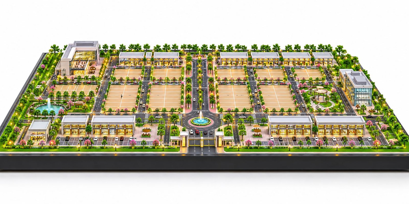
Intelligent Factory Communication Network Model for Smart Industrial Automation
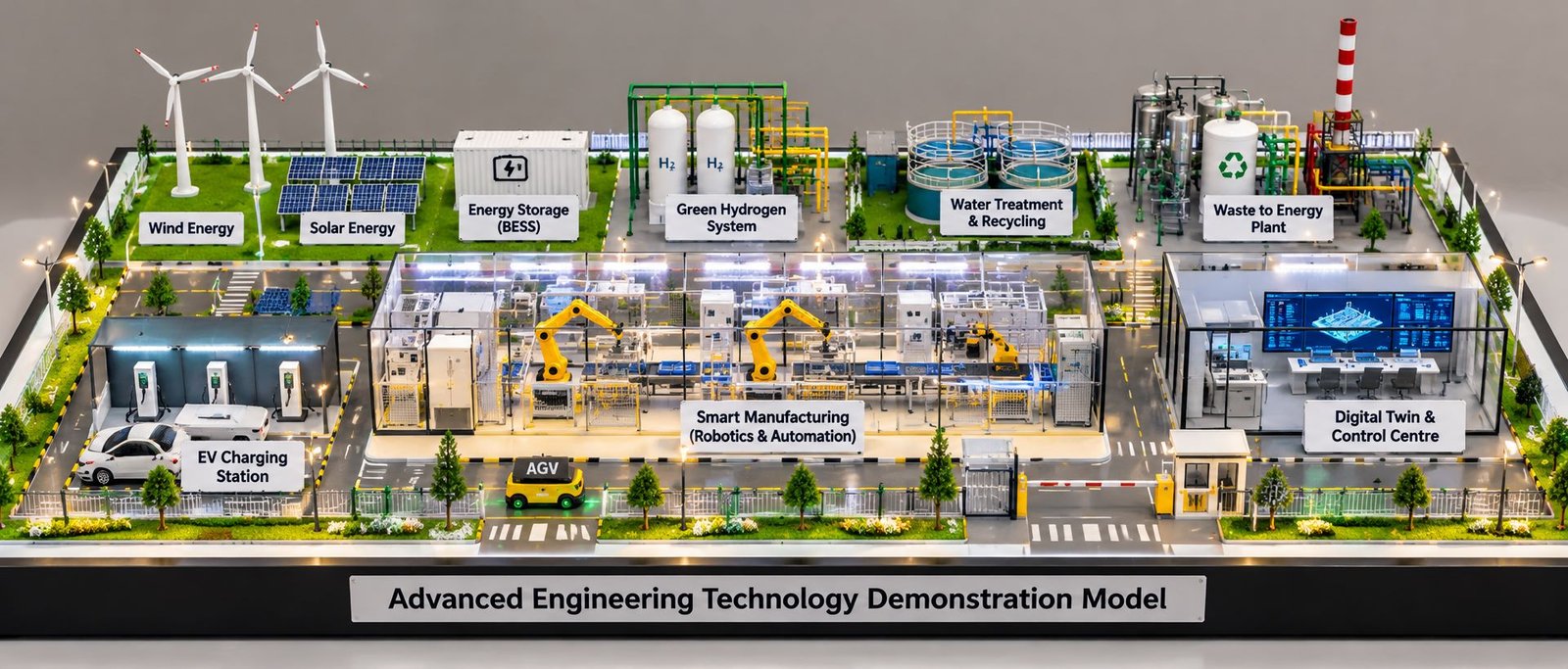
An Intelligent Factory Communication Network Model is a physical scale model that demonstrates how industrial machines, sensors, robotic systems, controllers, and monitoring stations communicate within a modern manufacturing facility. It provides a visual understanding of industrial connectivity, automated production, real-time data exchange, and smart factory operations.
As industries adopt advanced automation technologies, communication networks have become essential for coordinating production activities. Therefore, an intelligent factory model helps architects, industrial engineers, automation specialists, students, and project teams understand how different systems work together.
Moreover, a professionally designed model can represent industrial Ethernet networks, programmable logic controllers (PLCs), Industrial Internet of Things (IIoT) devices, wireless communication systems, and centralized monitoring equipment. These elements create a practical representation of a connected industrial environment.
What Is an Intelligent Factory Communication Network Model?
An intelligent factory communication network model is a miniature representation of a manufacturing facility in which industrial equipment is connected through communication and automation systems. The model illustrates how information moves between machines, control panels, sensors, and monitoring stations.
Unlike a conventional factory layout model, an intelligent factory model focuses on both physical production equipment and the communication infrastructure that supports it. For example, it can show how a sensor detects a product, how a PLC processes the signal, and how the control system coordinates the next operation.
Furthermore, the model can demonstrate how different production areas exchange information to improve operational visibility. It may include assembly lines, conveyors, robotic workstations, inspection equipment, industrial servers, and network switches.
These models are particularly useful when a company needs to explain a complex automation system during a technical presentation, project review, exhibition, or educational demonstration.
Key Features of an Intelligent Factory Network
An intelligent factory network combines multiple technologies to support coordinated industrial operations. Its main features include connected machinery, centralized monitoring, automated data collection, and communication between different production systems.
For instance, sensors can provide equipment status information, while PLCs control specific operations. Industrial network switches connect compatible devices, and monitoring stations display important operating information.
In addition, wireless connectivity may be represented where appropriate. The exact configuration depends on the factory layout, communication technology, and purpose of the project.
A scale model brings these components together in one visual arrangement, making the overall network easier to understand.
How Industrial Communication Networks Connect Factory Equipment
Industrial communication networks allow machines and control systems to exchange information through defined communication protocols. Depending on the application, these connections may use industrial Ethernet, fieldbus systems, wireless technologies, or a combination of different methods.
For example, a conveyor sensor can send a signal to a PLC when a product reaches a particular position. The PLC then controls the relevant equipment, while connected monitoring software displays the operating status.
Similarly, robotic stations can coordinate their activities with conveyors and inspection systems. Consequently, a connected factory can achieve more consistent production and improved process visibility.
A physical model can represent these relationships through miniature network devices, visible cable routes, control cabinets, and clearly arranged equipment.
Main Components of an Intelligent Factory Communication Network
A well-designed intelligent factory communication network model includes the major elements required to explain the factory’s production and communication architecture. Each component has a specific purpose within the overall arrangement.
The final selection depends on the project’s technical requirements, available space, presentation goals, and desired level of detail.
Industrial IoT Sensors and Connected Devices
Industrial Internet of Things sensors collect information from machinery, production lines, and the surrounding environment. Depending on their function, these devices may measure temperature, pressure, vibration, position, speed, or other operating conditions.
In a scale model, sensors can be represented near conveyors, robotic stations, motors, pumps, and other industrial equipment. Their placement helps viewers understand where data originates within the production environment.
Moreover, connected devices can communicate operating information to compatible controllers or monitoring platforms. This information supports equipment monitoring, process analysis, and maintenance planning.
For realistic presentation, miniature sensors should be positioned logically rather than scattered randomly across the factory layout.
PLC Controllers and Automation Systems
Programmable logic controllers are widely used to control industrial machinery and automated processes. They receive input signals, execute programmed logic, and generate outputs that operate connected equipment.
An intelligent factory model may include miniature PLC cabinets, control panels, motor-control equipment, and automation stations.
For example, a PLC can control a conveyor motor, coordinate a robotic operation, or respond to a sensor signal. Multiple controllers may also exchange information through an appropriate industrial communication network.
Consequently, showing PLCs in suitable locations helps explain the relationship between machine-level control and the broader factory network.
Industrial Ethernet Switches and Network Cabling
Industrial Ethernet switches connect compatible network devices and help route data between systems. They are commonly used to connect controllers, monitoring equipment, industrial computers, and other network-enabled devices.
Network cabling provides the physical communication path between connected equipment. In a physical model, miniature cables can run through organized routes, cable trays, and designated connection points.
However, the model should distinguish communication wiring from power cables wherever practical. This makes the arrangement more understandable and visually realistic.
The network layout should also reflect a plausible architecture. For example, a model may represent a central industrial switch connected to several production areas, with additional switches serving local equipment where required.
Wireless Communication and Monitoring Systems
Wireless communication can support selected industrial applications, including mobile equipment monitoring, remote access, and communication with compatible wireless devices.
A factory model may represent wireless access points, antennas, handheld monitoring equipment, or connected mobile platforms. These components should be positioned according to the intended coverage area and factory layout.
Nevertheless, wireless connectivity should not be represented as a replacement for every wired connection. Many industrial systems use a combination of wired and wireless technologies because different applications have different reliability, latency, security, and environmental requirements.
By presenting both connection types appropriately, the model provides a more realistic view of industrial communication.
Servers and Factory Control Stations
Servers and industrial computers may support production monitoring, data collection, visualization, reporting, and communication with higher-level software systems.
A model can include a small server rack, an operator workstation, a human-machine interface (HMI), or a supervisory control and data acquisition (SCADA) station.
These components help explain how information collected from machines becomes available to operators and production managers.
For instance, an operator may view equipment status, production progress, alarms, or process measurements through a monitoring interface. Therefore, a clearly positioned control station helps connect the physical factory layout with its digital monitoring environment.
How an Intelligent Factory Communication Network Works
An intelligent factory communication network combines sensing, control, communication, and monitoring. Although the exact arrangement varies by industry, the basic process can be explained through a typical automated production line.
Data Collection from Industrial Machines
The process begins when sensors and connected devices collect information from equipment. These devices may detect product position, measure operating conditions, or identify whether a machine is running.
Next, the information is transmitted to a controller or another compatible system. The receiving device processes the data according to the configured control logic.
For example, a sensor installed beside a conveyor can detect an approaching product. The controller can then trigger a sorting mechanism or coordinate the next production operation.
In the model, sensors should be placed near the equipment they monitor so that viewers can understand the origin of the signals.
Communication Between PLCs, Sensors, and Robots
Once data has been collected, industrial controllers use the information to coordinate equipment operations. Depending on the system architecture, controllers may communicate directly with other devices or exchange information through industrial network infrastructure.
For instance, a robotic workstation may receive information about product availability from a conveyor control system. The robot can then perform its assigned task when the required conditions are satisfied.
Similarly, inspection equipment can communicate results to a controller, which may direct products toward different processing or handling areas.
A physical model can illustrate these relationships through logical equipment placement, connected control cabinets, and clearly arranged communication routes.
Real-Time Monitoring Through Connected Systems
Monitoring systems collect and display information from compatible controllers, machines, and sensors. Depending on the configuration, operators can observe equipment status, production progress, alarms, and selected operating parameters.
This visibility helps teams identify abnormal conditions and respond to operational changes more effectively.
Furthermore, historical data can support production analysis and maintenance planning. However, the availability of real-time information depends on the installed devices, network design, software, and communication settings.
An intelligent factory scale model can represent this monitoring arrangement by placing the control room or operator station in a visible location and showing its relationship with the production areas.
Technologies Used in Intelligent Factory Networks
Modern factory communication systems may use several technologies together. The appropriate selection depends on the machinery, required response times, network architecture, data security, and operational environment.
Industrial Internet of Things (IIoT)
The Industrial Internet of Things connects industrial equipment, sensors, and monitoring systems to collect and exchange useful operational data.
IIoT applications may support equipment condition monitoring, production tracking, energy management, and maintenance analysis.
For example, vibration sensors can provide information that helps maintenance teams identify unusual equipment behaviour. Similarly, production sensors can report counts or operating states to a compatible monitoring platform.
An intelligent factory model can represent IIoT through miniature sensors, connected machines, control cabinets, and monitoring stations.
Industrial Ethernet and Profinet Communication
Industrial Ethernet supports data communication between compatible industrial devices. Depending on the application, technologies such as PROFINET can connect controllers, distributed I/O devices, drives, and other automation equipment.
These systems help coordinate machine operations and provide communication between different parts of a production line.
In a physical model, industrial Ethernet switches, network cables, and PLC cabinets can illustrate the main communication infrastructure.
However, the selected protocol should match the intended technical concept. A presentation model can illustrate the architecture without claiming that a particular protocol is implemented unless the project specification confirms it.
Wireless Networks and Remote Monitoring
Wireless technologies can connect selected industrial devices without requiring a physical cable for every communication link. Their applications may include mobile equipment, monitoring devices, and certain remote-control or data-collection systems.
The model can show wireless access points and compatible equipment alongside the wired network.
At the same time, the design should communicate that industrial wireless networks require suitable coverage, interference management, access control, and security measures.
This balanced representation helps viewers understand how wired and wireless technologies can coexist within a connected factory.
Cloud Computing and Industrial Data Analytics
Some factories transfer selected operational data to cloud platforms or other centralized computing environments for analysis, reporting, and long-term storage.
Data analytics can help identify production patterns, monitor equipment performance, and support planning decisions. In some applications, edge computing processes data closer to the equipment to reduce communication delays or limit unnecessary data transfers.
A scale model may represent these functions using an industrial server rack, a monitoring workstation, and a clearly defined connection to an external data-processing system.
Nevertheless, cloud connectivity should be included only when it fits the project’s intended architecture.
Applications of Intelligent Factory Communication Models
Intelligent factory communication network models are useful in industries where automation, connected equipment, and coordinated production processes are important. Their physical format makes technical concepts easier to present to audiences with different levels of engineering knowledge.
Smart Manufacturing and Automated Production Lines
Smart manufacturing facilities combine machinery, control systems, and communication networks to coordinate production activities.
A model can include conveyors, assembly stations, robotic arms, sensors, inspection equipment, and central monitoring systems. Together, these elements demonstrate how products move through a connected manufacturing environment.
Furthermore, the model can show how information from one workstation affects the operation of another.
This application is particularly useful for manufacturing companies, automation solution providers, technical institutions, and industrial exhibitions.
Industrial Robotics and Material Handling
Robotic systems are frequently used for assembly, material handling, welding, packaging, and other repetitive industrial tasks.
Their operation often depends on communication with sensors, controllers, conveyors, and safety systems.
An intelligent factory model can demonstrate how robotic workstations fit within a wider production network. For example, a robot may collect an item from a conveyor and transfer it to an inspection or packaging area.
The layout should provide enough space around each workstation to show the equipment clearly and represent realistic material movement.
Process Control and Equipment Monitoring
Process industries use automation and monitoring systems to manage equipment and maintain operating conditions. Depending on the industry, a model may include pumps, motors, tanks, pipelines, valves, control panels, and monitoring stations.
These components can be connected conceptually to represent how measurements and control signals move through an industrial system.
For example, a sensor may report a process measurement to a controller, which then adjusts a compatible actuator. The monitoring system can display the resulting operating condition.
This type of model is suitable for technical presentations involving manufacturing, energy, water treatment, and process engineering.
Predictive Maintenance and Production Management
Predictive maintenance uses equipment data and analytical methods to identify signs of developing faults or changes in operating condition.
Connected sensors can provide information about vibration, temperature, operating hours, or other relevant measurements. Maintenance teams may use this information to investigate potential problems before equipment failure occurs.
A scale model can represent this process through monitored motors, sensor locations, communication devices, and a central workstation.
In addition, a production management display can illustrate how equipment status and production information are brought together for operational review.
Design and Development of an Intelligent Factory Scale Model
Developing a realistic intelligent factory communication network model requires careful planning. The design should communicate the technical concept clearly while maintaining accurate equipment proportions and a practical physical layout.
Planning the Factory Layout and Communication Architecture
The design begins with understanding the purpose of the model. A manufacturing demonstration, an automation project presentation, and an engineering education model may require different levels of detail.
Next, the major production areas are identified. These may include assembly lines, material handling zones, inspection stations, machine cells, control cabinets, and operator areas.
The communication architecture is then mapped onto the layout. Designers identify the main network devices, relevant connections, and the relationships between local controllers and centralized monitoring systems.
Where required, separate visual conventions can be used for power, control, and communication cables.
As a result, the completed model can explain both the factory arrangement and the intended information flow without overcrowding the display.
Selecting Machinery, Network Devices, and Model Materials
Material selection influences the model’s appearance, strength, weight, and level of detail. Depending on the project, construction may use acrylic, foam board, MDF, plastic sheets, resin components, 3D-printed parts, and other suitable materials.
Miniature machinery, control cabinets, server racks, conveyors, and robotic stations can be fabricated or assembled according to the design requirements.
In addition, the baseboard should support the complete arrangement and provide sufficient room for equipment, pathways, cable routes, and maintenance access areas.
A wide, low-height layout can be particularly effective when the objective is to show multiple connected production zones in one view.
Representing Cable Routes and Wireless Connectivity
Communication routes should be arranged logically so viewers can follow the network between devices. Small cables, miniature trays, connectors, and clearly defined connection points can help represent the physical infrastructure.
However, excessive wiring can make the model difficult to understand. Therefore, cables should be organized into clean routes and placed where they contribute to the explanation.
Wireless devices should also be positioned sensibly. Their placement may illustrate the intended coverage of selected areas, although a miniature display cannot independently verify actual radio performance.
If the model requires labels or a legend, these should remain concise and readable without distracting from the physical equipment.
Integrating Control Panels and Monitoring Stations
Control panels and monitoring stations help explain how operators interact with automated equipment. A model can include PLC cabinets, HMI screens, industrial computers, and server racks where appropriate.
The control area should have a clear relationship with the production floor. For example, a central monitoring station may be positioned beside the main production area, while local control cabinets are placed near specific machinery.
Furthermore, the model can use small indicator lights or display elements when they serve a clear purpose. Decorative lighting should not be confused with functional network connections.
The objective is to produce a credible industrial presentation model rather than an arrangement of disconnected miniature objects.
Benefits of Intelligent Factory Communication Network Models
A professionally designed intelligent factory model offers several advantages for technical communication, training, and project presentation.
Clear Visualization of Industrial Connectivity
Industrial communication systems can be difficult to explain through written documents alone. A physical model makes the relationships between machines, controllers, sensors, and monitoring equipment easier to see.
Viewers can follow the arrangement of production areas and understand how the communication infrastructure connects different parts of the factory.
Consequently, the model can support discussions between engineering teams, management, clients, and other stakeholders.
Better Understanding of Automation Processes
The model helps explain the relationship between data collection, control logic, equipment operation, and monitoring.
For example, a connected conveyor and robotic workstation can demonstrate how several industrial devices participate in a single production process.
Similarly, the placement of sensors and controllers can make the roles of individual components easier to understand.
This visual approach is useful for engineering demonstrations, classroom instruction, and technical presentations.
Improved Technical Presentations and Training
A detailed scale model can communicate complex concepts in a structured and engaging format. It provides a physical reference that presenters can use when explaining network architecture, equipment placement, and production flow.
In addition, customized models can focus on the technologies most relevant to the audience. An industrial automation presentation may emphasize PLCs and network devices, while an Industry 4.0 demonstration may include IIoT sensors and monitoring systems.
As a result, the presentation can remain focused on the intended technical objectives.
Support for Industry 4.0 Demonstrations
Industry 4.0 combines connected equipment, automation, data exchange, and digital technologies to improve industrial operations.
An intelligent factory communication network model can visually bring these concepts together through connected production equipment, communication infrastructure, and centralized monitoring.
Although a physical model does not automatically reproduce the performance of a live industrial network, it can effectively illustrate the relationships between its major components.
Choosing an Intelligent Factory Model for Industrial Presentations
Selecting the right model requires a clear understanding of its intended use. The best design is not necessarily the one with the greatest number of components. Instead, it is the one that communicates the required technical information accurately and clearly.
Important Design and Display Requirements
Before development begins, define the main purpose of the model. Identify the equipment, communication technologies, production areas, and monitoring functions that must be represented.
The physical layout should remain balanced, with sufficient space between major components. Network devices should be easy to identify, while cable routes should remain organized and understandable.
Moreover, the baseboard, material finish, equipment proportions, and overall presentation should suit the display environment.
If the model will be transported frequently, construction strength and the protection of delicate components should also be considered.
Customization for Different Industrial Applications
Every industrial facility has different operational requirements. A packaging factory may focus on conveyors, sensors, sorting equipment, and robotic handling. An automotive facility may emphasize assembly stations, robotic cells, inspection systems, and coordinated material movement.
Similarly, a process plant may require pumps, motors, control cabinets, pipelines, and monitoring equipment.
Therefore, the model should be customized to match the intended industrial application rather than following a generic layout.
PAL Design Models provides scale model making services for architectural, industrial, engineering, and presentation requirements. A project-specific design can help communicate the layout, equipment arrangement, and technical concept required for a particular presentation.
Frequently Asked Questions About Intelligent Factory Communication Models
What Does an Intelligent Factory Communication Network Model Show?
It shows how industrial machines, sensors, controllers, network devices, and monitoring systems can connect within a manufacturing facility. The model helps explain the relationship between production equipment and industrial communication infrastructure.
Which Technologies Are Represented in an Intelligent Factory Model?
Depending on the project, the model may represent Industrial IoT, PLC automation, industrial Ethernet, PROFINET, wireless communication, server systems, HMI stations, and SCADA monitoring.
The selected technologies should reflect the intended factory architecture.
Can an Intelligent Factory Model Include PLCs and Industrial IoT?
Yes. A customized model can include miniature PLC cabinets, sensors, connected machinery, industrial network switches, and monitoring equipment. Their placement can illustrate how control signals and operational data move through the factory.
Who Can Use an Intelligent Factory Communication Model?
Manufacturers, automation companies, industrial engineers, educational institutions, project consultants, and exhibition teams can use these models for technical presentations, training, demonstrations, and project visualization.
Can the Model Demonstrate a Working Communication Network?
A static scale model illustrates the network layout and component relationships. If the project requires actual working communication, additional hardware, controllers, software, and testing may be needed. The final functionality depends on the agreed technical scope.
Conclusion
An Intelligent Factory Communication Network Model provides a clear visual representation of connected industrial equipment, automation systems, and communication infrastructure. By combining miniature machinery, sensors, PLC cabinets, network switches, organized cabling, and monitoring stations, it helps explain how modern manufacturing systems coordinate their operations.
Furthermore, a carefully planned model can make complex industrial concepts easier to communicate during technical presentations, engineering training, exhibitions, and project reviews. Its effectiveness depends on accurate component selection, a logical factory layout, realistic detailing, and clear representation of communication pathways.
For organizations presenting smart manufacturing or industrial automation projects, a customized intelligent factory model can serve as a valuable visual tool for explaining the relationship between machinery, connectivity, and production management.