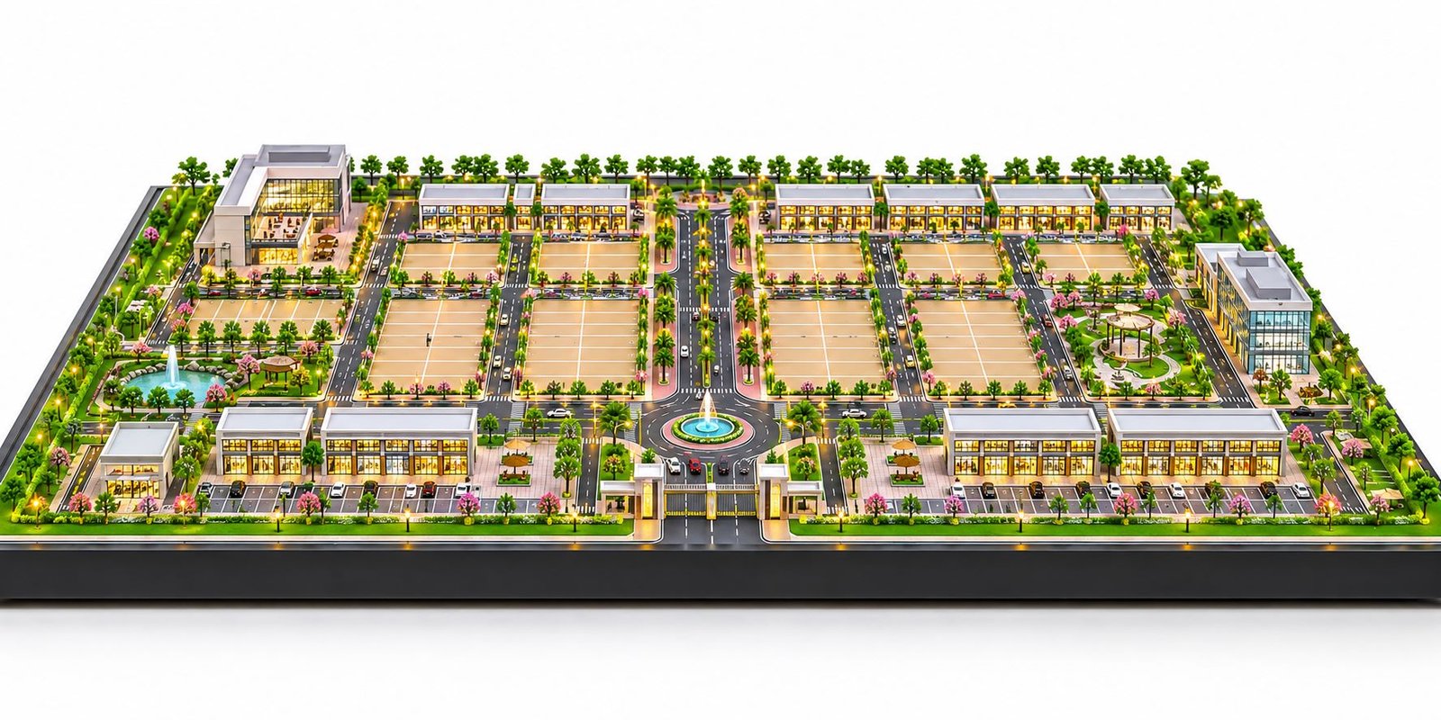
PCB Manufacturing Factory Model for Industrial Project Presentation
Introduction to PCB Manufacturing Factory Model Making
A PCB Manufacturing Factory produces printed circuit boards used in computers, mobile phones, medical devices, industrial machines, vehicles, and communication equipment. A detailed PCB Manufacturing Factory Model presents this type of industrial facility as a physical scale model, showing its buildings, production lines, machinery, testing areas, warehouses, and utility systems.
As the electronics industry grows, manufacturers need clear ways to present new factories and production facilities. Therefore, a physical factory model can help explain a complex industrial project to investors, engineers, architects, clients, and management teams. Instead of relying only on technical drawings, viewers can see the proposed layout in three dimensions.
For example, a printed circuit board production plant may include drilling machines, lamination presses, copper plating lines, etching equipment, solder mask sections, inspection stations, and packing areas. In addition, the site may contain raw material storage, electrical rooms, wastewater treatment facilities, offices, and internal roads.
A well-designed industrial model brings these elements together on one baseboard. As a result, viewers can understand the relationship between the factory buildings and the manufacturing process.
PAL Design Models provides architectural and industrial scale model-making services for project presentations. This blog explains the main features, design process, materials, benefits, and cost factors involved in creating a detailed PCB factory model.
What Is a PCB Manufacturing Factory Model?
A PCB Manufacturing Factory Model is a miniature physical representation of a printed circuit board production facility. It shows the factory layout, manufacturing departments, major machines, material handling areas, and supporting infrastructure.
Unlike a simple building model, this type of industrial model focuses on both the building design and the production arrangement. For instance, it can show how raw materials enter the facility, move through different processing departments, and reach the final inspection and packing sections.
The model maker uses the project’s site plan, architectural drawings, equipment layout, and other technical information to create an accurate display. Furthermore, the design can include miniature machines, internal roads, loading bays, storage racks, utility equipment, and landscaped areas.
A PCB factory scale model can range from a basic site layout to a highly detailed presentation model. The final design depends on the factory size, the available drawings, the required scale, and the intended use.
Why Is a PCB Manufacturing Factory Model Important?
Electronics production facilities often contain several departments and specialised machines. Consequently, a two-dimensional drawing may not communicate every detail clearly to a non-technical viewer.
A physical model offers a more direct way to present the proposed facility. It also gives different project teams a shared visual reference.
Clear Industrial Layout Presentation
A manufacturing plant may include production halls, warehouses, laboratories, utility rooms, offices, and loading areas. A detailed model shows these sections together, making the overall arrangement easier to understand.
For example, viewers can identify the raw material storage area and follow the route towards the production departments. Similarly, they can see the connection between testing, finished goods storage, and dispatch.
Better Communication With Investors and Clients
Companies often use industrial models during project proposals, investment meetings, and management presentations. In these situations, a physical display can explain the proposed facility more clearly.
Moreover, a model gives viewers a quick overview of the building arrangement and the main production areas. However, it should support technical documents rather than replace engineering calculations or financial reports.
Support for Factory Planning
Architects, production planners, and engineers may need to discuss the relationship between buildings, equipment, roads, and utility areas. A scale model helps them view these elements together.
As a result, the team can discuss the layout more effectively. Nevertheless, engineers must still check machine clearances, safety routes, service access, and process requirements using the appropriate technical drawings.
Industrial Exhibition and Marketing Display
A PCB manufacturing plant model can serve as a display at industrial exhibitions, company offices, technology events, and project launches.
For instance, an electronics manufacturer can use the model to introduce a planned production facility to visitors. In addition, clearly visible machines and labelled departments help explain the factory to people who do not work in electronics manufacturing.
Main Sections of a PCB Manufacturing Factory Model
The layout of a PCB manufacturing facility depends on its products, production methods, and capacity. Therefore, the model should follow the actual project drawings rather than use a generic arrangement.
Raw Material Storage and Receiving
PCB production uses materials such as copper-clad laminates, copper foil, resin-based materials, chemicals, and solder mask supplies.
The model can show a receiving area, storage racks, material pallets, and loading bays. Furthermore, the warehouse should connect logically with the relevant production departments.
This arrangement helps viewers understand how materials enter the factory and move towards the manufacturing process.
Cutting and Material Preparation
Some PCB production processes require large sheets to be cut into suitable sizes before further processing. The facility may also contain preparation tables and material handling equipment.
A detailed model can include cutting machines, workstations, storage racks, and transfer areas. Meanwhile, floor markings can help distinguish the preparation section from nearby departments.
PCB Drilling Section
Drilling creates holes for component leads and electrical connections. Depending on the board design, manufacturers may use mechanical drilling, laser drilling, or other specialised methods.
The model maker can represent drilling machines as miniature industrial units. In addition, the design may include material carts, inspection stations, and work areas.
Because drilling equipment can occupy an important part of the production layout, its position should match the supplied factory plan.
Lamination and Layer Bonding
Multilayer printed circuit boards require several layers to be bonded together. During lamination, specialised presses apply controlled heat and pressure to join these layers.
The model can show lamination presses, preparation areas, and nearby handling equipment. Consequently, viewers can understand where this process takes place within the production facility.
Copper Plating Department
Copper plating helps create conductive connections through drilled holes in many PCB designs. Depending on the process, the plant may include plating lines, processing tanks, and supporting equipment.
A physical model can represent these components as a separate production zone. It may also show chemical storage and wastewater treatment facilities when the project drawings include them.
However, the model maker should not add unsupported equipment or assume a particular process arrangement.
Etching and Circuit Pattern Formation
PCB manufacturing often uses imaging and etching processes to form the required copper patterns. These stages need suitable equipment and controlled working conditions.
A PCB Manufacturing Factory Model can show the etching section as a distinct department within the main production hall. In addition, transfer routes can connect this area with the preceding and following production stages.
As a result, viewers can follow the manufacturing flow more easily.
Solder Mask Application
A solder mask protects selected PCB areas and helps prevent unwanted solder connections. Green is a common colour, although manufacturers also use other colours.
The model can include coating equipment, curing units, workstations, and department labels. Furthermore, the layout can show how this section connects with the relevant production stages.
Screen Printing and Marking
Some PCB processes add symbols, text, component references, and other markings to the board. Depending on the production method, the factory may use screen printing or other marking equipment.
A detailed model can show printing machines, inspection tables, and small material racks. These components add useful detail while keeping the factory layout easy to understand.
Inspection and Testing Area
Quality checks are essential in PCB manufacturing. Depending on the product and process, a factory may use automated optical inspection, electrical testing, and other inspection systems.
The model can show testing machines near the appropriate production stages. In addition, a separate quality control room or laboratory can be included when the project design requires it.
This arrangement explains how the factory checks its products before packing and dispatch.
Final Finishing and Packing
Some production lines include routing, cleaning, finishing, and final preparation before the boards are packed.
The model can show these areas between the main production hall and the finished goods warehouse. Similarly, miniature packing tables, cartons, storage racks, and loading bays can represent the dispatch process.
As a result, viewers can understand how the facility handles products from production to delivery.
Factory Buildings and Infrastructure Details
A complete PCB Manufacturing Factory Model should show more than production machinery. It should also represent the buildings, access routes, and utility systems that support the plant.
Main Production Building
The main production hall often occupies a large part of the site. It may contain several departments, machine areas, service corridors, and workspaces.
An open-roof or cutaway design can reveal the machinery inside the building. In contrast, a closed structure may suit projects that focus mainly on the exterior architecture.
Therefore, the model maker should select the building style according to the purpose of the presentation.
Electrical Substation and Power Systems
PCB production equipment requires a suitable electrical supply. Consequently, the facility may include electrical rooms, transformers, switchgear, backup power systems, and related infrastructure.
The model can show these facilities in the planned service area. Moreover, clear separation between the production building and utility structures can make the overall layout easier to read.
Cooling and Compressed Air Systems
Some production machines need cooling water or compressed air. For this reason, a factory may include chillers, pumps, compressors, and supporting equipment.
A detailed industrial model can represent these facilities as miniature utility blocks. Labels can also identify the main systems without adding excessive text.
Chemical Storage and Wastewater Treatment
Certain PCB manufacturing processes use chemicals and generate wastewater that requires suitable treatment. Therefore, the plant may include chemical storage, drainage systems, and an effluent treatment facility.
The model can show treatment tanks, process units, pipes, and service roads when these features appear in the project plan. In addition, placing these facilities in their planned locations helps maintain an accurate layout.
Warehouse and Administration Building
Many factories have separate buildings for raw materials, finished goods, offices, meeting rooms, and staff facilities.
A physical model can show these structures around the main production hall. Furthermore, it can include visitor parking, staff parking, security gates, and loading areas.
Internal Roads and Loading Bays
Internal roads connect the entrance with production buildings, warehouses, parking areas, and loading bays. Therefore, the model should keep these routes visible.
Miniature trucks, road markings, pedestrian paths, and loading platforms can improve realism. However, vehicles and decorative elements should not hide the main buildings or production equipment.
How to Design a PCB Manufacturing Factory Model
A successful model begins with accurate project information. After reviewing the drawings, the model maker can plan the scale, baseboard, equipment, and finishing details.
Review the Project Drawings
First, collect the site plan, building drawings, equipment layout, production arrangement, and utility information. These documents help the model maker understand the proposed factory.
Next, confirm which drawing version the team should follow. Since layouts may change during planning, using the correct version helps prevent avoidable errors.
Confirm the Display Purpose
The client should explain whether the model will support a project proposal, factory planning review, exhibition, or investor presentation.
For example, an exhibition model may need a strong overall appearance and clearly visible buildings. In contrast, a technical presentation may require more internal machinery and production details.
Therefore, the design should reflect the intended use.
Select the Scale and Dimensions
The scale determines the size of the miniature factory compared with the real facility. A large site may require a smaller scale to fit the complete layout on the baseboard.
However, the model must still show the important machines and building details. Consequently, the model maker should consider both site dimensions and viewing distance before finalising the scale.
Plan the Baseboard
The baseboard supports the factory buildings, roads, production areas, and utility blocks. For a website feature image or presentation display, a wide, low-height layout can show more of the site from a single angle.
First, place the main buildings and production halls. Next, add the roads, warehouses, parking, and supporting facilities.
This approach keeps the layout organised. In addition, it helps prevent decorative features from blocking important details.
Fabricate Buildings and Equipment
The model maker can use suitable materials to create miniature buildings, machines, tanks, pipes, and other components.
Furthermore, 3D printing can help produce complex equipment shapes and repeated parts. The team should choose fabrication methods according to the selected scale and required finish.
Add Labels and Lighting
Labels can identify major departments such as drilling, lamination, plating, etching, inspection, and packing. In addition, LED lighting can highlight selected buildings and production areas.
However, labels should remain readable without overcrowding the baseboard. Similarly, lighting should improve visibility rather than distract viewers.
Complete the Final Inspection
Finally, check the building positions, machine visibility, road layout, surface finish, and lighting. If the model uses an open-roof design, make sure that the main equipment remains visible from the intended viewing angle.
This final review helps the model maker identify problems before delivery.
Materials Used for PCB Manufacturing Factory Model Making
The choice of materials depends on the model dimensions, design complexity, and display requirements.
Acrylic Sheets
Acrylic works well for transparent covers, windows, selected machine details, and protective enclosures. In addition, an acrylic cover can help protect the finished display from dust.
PVC Sheets
PVC sheets suit many miniature walls, equipment panels, building parts, and machine covers. The model maker can cut and assemble them according to the design.
Foam Board
Foam board is useful for lightweight building blocks and simple structures. Therefore, it can help create clean shapes without adding excessive weight.
MDF and Wood
MDF and wood can support the baseboard and selected structural components. They provide a firm foundation for larger industrial displays.
3D-Printed Components
3D printing can produce detailed machine housings, pipes, tanks, and custom equipment parts. Moreover, it can help create consistent components for repeated machinery.
Paint, Labels, and LED Lighting
Paint distinguishes buildings, roads, and production zones. Meanwhile, labels identify departments, and LED lighting highlights selected areas.
The model maker should use these features carefully so that the factory remains clear and realistic.
Benefits of a Custom PCB Manufacturing Factory Model
A custom industrial model can support several business and project requirements.
Easier Understanding of Complex Layouts
Factory drawings contain technical symbols, dimensions, and equipment references. In contrast, a physical model presents the layout as a three-dimensional display.
As a result, viewers can understand how the departments fit inside the facility.
Stronger Project Presentations
A detailed model gives the presentation team a clear visual reference. For example, it can help explain the planned factory to clients, management, and investors.
Furthermore, the model can show the relationship between the production halls and supporting facilities.
Better Team Discussions
Architects, engineers, and production planners can use the same physical display during discussions. Therefore, they can review building access, equipment positions, and material movement more clearly.
Effective Exhibition Display
A realistic factory model can attract attention at industrial exhibitions and company events. In addition, visible machinery and clearly marked departments can help visitors understand the manufacturing process.
Support for Planning Reviews
A scale model can help teams review the overall arrangement of buildings, roads, and production areas. Nevertheless, professional engineering checks remain necessary for safety, machine clearances, and process requirements.
Factors That Affect PCB Factory Model Cost
The cost of a custom model depends on several project details. Therefore, the model maker should review the drawings before preparing a quotation.
Factory Size and Model Dimensions
A large site may require a larger baseboard or a smaller model scale. Both choices affect material use and fabrication time.
Number of Machines and Departments
A simple factory layout requires less work than a model containing many machines, tanks, conveyors, and utility systems. Similarly, custom equipment parts may need additional design and fabrication time.
Level of Detailing
A basic model may show buildings and main production zones. However, a detailed presentation model may include miniature machines, storage racks, pipes, vehicles, labels, and lighting.
Therefore, the client should identify the essential details before fabrication begins.
Materials and Finishing
Different materials offer different finishes and levels of detail. The model maker selects suitable options according to the project requirements.
Lighting, Covers, and Installation
LED lighting and protective covers may improve the display, but they also add to the work. In addition, large models may require special packing, transport, and installation.
For this reason, the client should confirm these requirements at the beginning of the project.
Who Needs a PCB Manufacturing Factory Model?
Several organisations may benefit from a custom PCB factory scale model.
Electronics manufacturers can use the model to present a proposed production facility or explain an existing plant.
Industrial consultants and project planners can use it to communicate the proposed site layout to clients and project teams.
Architects and engineering consultants may need a physical model for factory design presentations, expansion proposals, or industrial planning reviews.
Investors and management teams can use the display to understand the overall arrangement of a proposed facility. However, they should also review the relevant technical and financial information.
Exhibition and marketing teams may display the model at trade fairs, technology events, and company offices.
The required design depends on the purpose. Therefore, the client should share the project brief, drawings, preferred dimensions, and level of detail before fabrication starts.
How to Choose an Industrial Model-Making Company
Choosing a suitable model maker is important for achieving a clear and realistic result.
First, review examples of industrial scale models and factory layouts. Look for visible buildings, clearly represented machinery, neat baseboards, and accurate component placement.
Next, confirm that the company can work from the drawings available for the project. The team should understand the site plan, production layout, building dimensions, and display requirements.
In addition, discuss the scale, materials, lighting, labels, protective cover, delivery, and installation. These details help both sides agree on the expected result.
Finally, confirm the drawing version and review process before fabrication begins. This is particularly important when engineers update the factory layout during planning.
PAL Design Models works on architectural and industrial scale models for physical project presentations. For a PCB factory model, the project team should review the site layout, production drawings, equipment arrangement, and display requirements before finalising the design.
Common Mistakes to Avoid
A detailed model can lose its value if the team overlooks visibility or layout accuracy. Therefore, review these common mistakes before completing the display.
Hiding Machinery Behind Walls
Closed buildings can hide the equipment inside. For this reason, an open-roof or cutaway design may work better when internal production areas are important.
Making the Model Too Tall
A tall display can make it difficult to see the entire site from one angle. In contrast, a wide, low-height layout can improve visibility across the factory.
Overcrowding the Baseboard
Too many machines, trees, vehicles, or labels can make the layout difficult to read. Therefore, leave enough space around the important features.
Ignoring the Production Flow
The model should follow the actual factory layout. Otherwise, placing departments in the wrong order may give viewers an incorrect understanding of the process.
Using Unclear Labels
Labels should use simple names and readable text. Moreover, they should match the project drawings and the terminology used by the client.
Adding Unsupported Features
The model maker should not add equipment or facilities that are absent from the approved layout unless the client requests them. After all, accurate representation is more important than unnecessary decoration.
Frequently Asked Questions
What Is a PCB Manufacturing Factory Model?
It is a physical scale model of a printed circuit board production facility. It can show factory buildings, production machinery, testing areas, warehouses, utilities, and internal roads.
What Details Can a PCB Factory Model Include?
The model can include drilling machines, lamination presses, plating lines, etching sections, solder mask areas, inspection equipment, packing departments, and utility facilities. However, the final details depend on the project drawings.
Can You Make a Custom PCB Manufacturing Plant Model?
Yes. A custom model can follow the supplied site plan, architectural drawings, equipment layout, and display requirements. Therefore, the client should confirm the dimensions and level of detail before fabrication begins.
Can the Model Show Machinery Inside the Factory?
Yes. An open-roof or cutaway design can make internal production areas visible. As a result, viewers can study the factory layout and machinery together.
Which Materials Are Used for Industrial Factory Models?
Common materials include acrylic, PVC sheets, foam board, MDF, wood, and 3D-printed components. The model maker selects them according to the design and required finish.
How Long Does PCB Factory Model Making Take?
The timeline depends on the factory size, drawing quality, number of machines, materials, and level of detail. Therefore, a reliable estimate requires a review of the project information.
What Information Is Needed for a Quotation?
The client should provide the site plan, factory layout, building drawings, equipment arrangement, preferred model dimensions, display purpose, and any requirements for lighting or protective covers. In addition, the client should share the expected delivery date.
Can the Model Be Used at an Industrial Exhibition?
Yes. A PCB factory scale model can support exhibitions, project launches, investor meetings, and company presentations. For this purpose, a wide layout with visible production areas can work well.
Conclusion
A PCB Manufacturing Factory Model turns a complex electronics production facility into a clear physical presentation. It can show the main buildings, manufacturing departments, machines, testing areas, warehouses, and utility systems on one baseboard.
The best results come from accurate drawings, a suitable scale, careful component placement, and clearly visible production details. In addition, the model maker should plan the building design, baseboard, labels, and lighting around the intended use.
For electronics manufacturers, architects, industrial consultants, and project teams, a custom PCB factory scale model can support planning reviews, project proposals, exhibitions, and investor presentations.
Ultimately, a well-designed model does more than show a factory building. It helps people see how the facility fits together, understand the production layout, and discuss the project with greater clarity.