Distributed Control System Model Making for Industrial Automation
A Distributed Control System plays an important role in modern industrial automation. It helps industries monitor equipment, manage process conditions, collect field data, and control different operations through connected controllers and operator workstations. A detailed Distributed Control System model presents these functions through a realistic physical miniature.
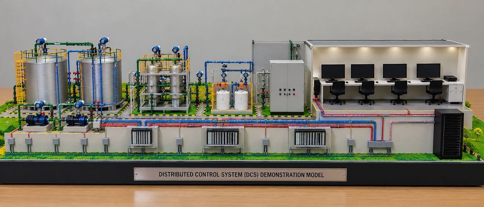
Unlike a simple electrical demonstration board, a complete model represents the industrial process and its control infrastructure together. It can include storage tanks, pumps, pipelines, valves, field instruments, chemical dosing units, control panels, controller modules, communication networks, server racks, and an operator control room.
Today, industrial automation companies, engineering colleges, EPC contractors, process plant designers, and technical training centres use physical models to explain complex engineering systems. In addition, manufacturers can display these models at exhibitions, technical presentations, training sessions, and project meetings.
A Distributed Control System demonstration model combines miniature industrial equipment with a carefully planned control architecture. The process equipment represents the physical plant, while the control room and electronic hardware represent the systems that monitor and manage industrial operations.
Furthermore, a well-designed model shows how individual components connect with one another. For example, a pressure transmitter represents a field instrument, a remote input/output panel represents signal collection, and a controller represents the hardware that processes information. Together, these elements explain the relationship between industrial equipment and process automation.
What Is a Distributed Control System Model?
A Distributed Control System model is a physical representation of an industrial automation environment. It illustrates how controllers, instruments, communication networks, and operator interfaces work together to monitor and control a process.
Industries use Distributed Control System technology in applications where many process variables and equipment units require coordinated control. These applications include chemical plants, power stations, oil refineries, water treatment facilities, pharmaceutical manufacturing, and other process industries.
A physical model represents the main equipment and communication architecture through miniature components. The process plant section shows where physical operations take place, while the control section represents how operators and controllers interact with the process.
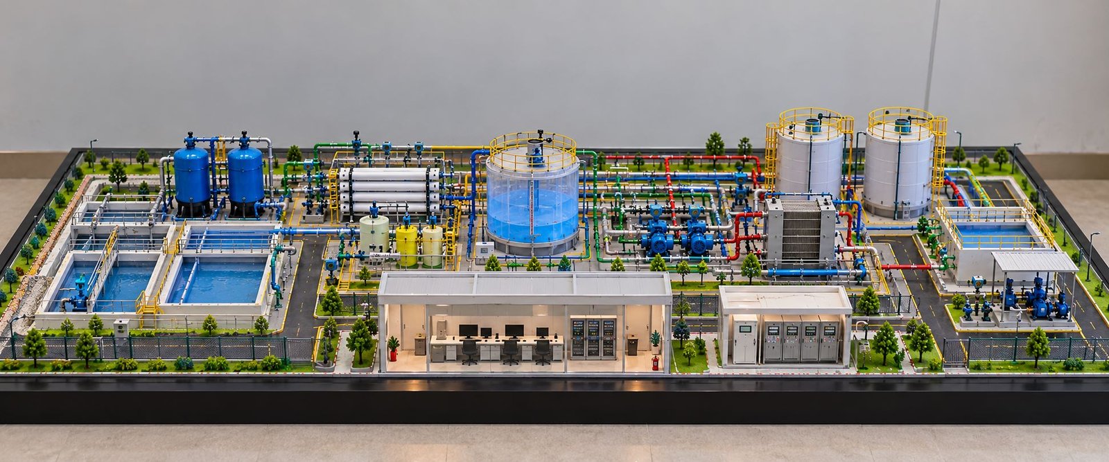
For example, a water treatment demonstration may include storage tanks, pumps, filters, dosing units, pipelines, and control instruments. Meanwhile, the Distributed Control System section may include controller modules, remote input/output panels, operator workstations, network switches, and server equipment.
As a result, viewers can understand the relationship between process equipment and its supporting control infrastructure in one physical display.
Difference Between a Distributed Control System Model and a Simple Control Panel Model
A simple control panel model usually focuses on switches, push buttons, indicators, relays, or a single controller. In contrast, a Distributed Control System model presents a wider industrial environment.
It connects field equipment with controller infrastructure, communication networks, operator workstations, and monitoring facilities. Consequently, viewers can understand how physical operations relate to control hardware and supervisory interfaces.
A complete model can also distinguish between the field layer, control layer, communication layer, and supervisory interface. This structure helps students, engineers, and visitors understand the broader architecture of industrial process automation.
Overall Layout of a Distributed Control System Demonstration Model
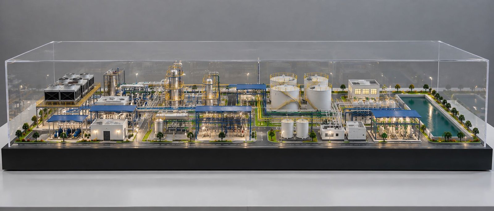
The layout plays an important role in making an industrial demonstration model easy to understand. A wide rectangular baseboard provides enough space for several technical areas without making the overall structure excessively tall.
Industrial Process Area in a Distributed Control System Model
The process area contains storage tanks, process vessels, pumps, pipelines, valves, and supporting structures. These components represent the physical plant where liquids or other materials move through different stages.
Storage tanks provide a clear starting point for understanding the process. Pipes connect the equipment, while pumps represent the machinery that moves fluid between selected sections.
Additionally, safety railings, access platforms, and miniature instruments make the equipment area look like a real industrial installation. Consistent spacing also helps viewers follow the process route across the model.
Central Control and Equipment Area
The central section contains the process control panel, equipment cabinets, controller modules, and associated connections. This area forms the visual link between the industrial process and the control room.
The control panel represents a local interface for monitoring or managing selected equipment. Meanwhile, the controller and remote I/O sections represent hardware that receives field signals and executes control logic.
Colour-coded cables or miniature conduits can illustrate communication and signal routes. These elements should follow a logical arrangement so viewers can distinguish the different equipment groups.
Control Room in a Distributed Control System Model
The control room represents the area where operators monitor process conditions and interact with the automation system.
A miniature room may include desks, chairs, computer monitors, and supporting equipment. Multiple workstations suggest that different screens or consoles may serve separate monitoring and operational tasks.
For a static physical model, the monitors can remain switched off. This approach maintains the appearance of a fabricated miniature rather than an illuminated digital illustration.
A separate server rack beside the control room represents computing equipment that may support data collection, historical records, and other configured system services.
Main Components of a Distributed Control System Model
A professional Distributed Control System demonstration model should represent the relationship between the physical process and its control equipment. Each component contributes to the overall layout and helps explain a different part of industrial automation.
Storage Tanks in a Distributed Control System Model
Storage tanks are among the most noticeable components in a Distributed Control System model. They represent vessels that hold liquids or other materials before, during, or after an industrial process.
The model can feature tall cylindrical tanks with metallic surfaces. Their height and diameter distinguish them from smaller process vessels and equipment cabinets.
A realistic miniature tank can include a cylindrical shell, top cover, support ring, and visible pipe connections. Depending on the design, the tank may also feature an access opening, vent connection, external ladder, or small nozzle fittings.
The metallic finish reproduces the appearance of industrial storage equipment. However, the surface should not appear excessively glossy because a controlled finish generally looks more realistic under studio lighting.
Tank Connections and Pipe Nozzles
Pipes enter or leave tanks through connection points known as nozzles. These connections represent the movement of material into a vessel or towards the next process stage.
The miniature model can show inlet and outlet pipes at different heights according to the intended arrangement. Small flanges and connectors improve the detail of the tank assembly.
In addition, the model can include level sensors or other instruments mounted on the tank wall or near the top. These details help demonstrate how the control system monitors tank conditions.
Tank Platforms and Safety Railings
Safety railings around elevated platforms represent protective barriers used near industrial equipment. Yellow railings provide a clear contrast against metallic tanks and coloured pipes.
The miniature platforms should have consistent heights, secure-looking supports, and evenly spaced vertical posts. Furthermore, ladders and access platforms can represent the facilities used for inspection and maintenance.
Although these details improve the appearance of the model, actual industrial safety structures must follow the applicable design requirements.
Pumps and Pipelines in a Distributed Control System Model
Pumps represent machinery that moves liquids between tanks, filters, dosing units, and other process equipment. In a water treatment or chemical process demonstration, they help explain how materials move through the system.
Miniature Pump Units
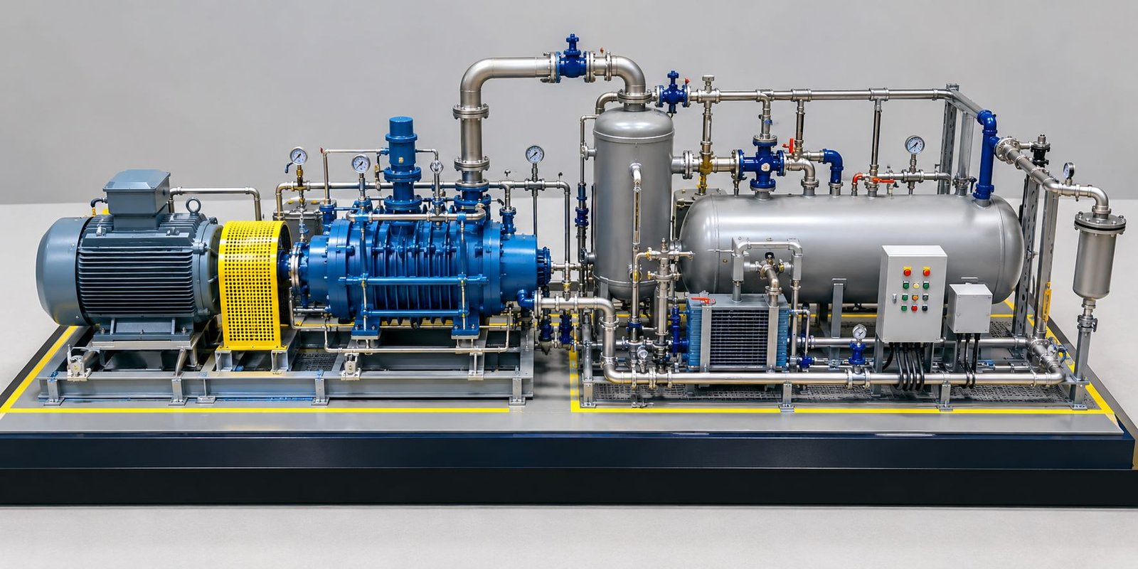
A realistic miniature pump may include a motor body, pump casing, mounting base, inlet connection, and discharge connection. These components make the equipment easier to identify.
Dark blue pump housings and metallic fittings can create a clear visual distinction from green or blue pipelines. Small mounting plates also help the pumps appear securely installed.
The pump assemblies should remain visible from the intended viewing angle. Therefore, the model maker should avoid placing large pipe sections directly in front of important equipment details.
Pump Inlet and Outlet Connections
The inlet pipe carries fluid towards the pump, while the outlet pipe carries it away. These routes should connect logically to the surrounding equipment.
Clean connections and properly aligned supports make the assembly look more realistic. In addition, consistent pipe diameters and suitable bends help maintain a professional appearance.
Pump Control and Monitoring
In an industrial Distributed Control System environment, pump operation may depend on control logic, process conditions, equipment interlocks, and operator commands.
A demonstration model can represent these relationships through field instruments, controller panels, and organised signal routes. If the model includes functional components, selected indicators can demonstrate operating states.
However, actual pump control arrangements depend on the plant design. The physical display should represent the intended system rather than suggest that every pump operates through an identical control configuration.
Pipeline Colours and Connections
Pipelines form a major visual feature of a physical Distributed Control System model. They connect tanks, pumps, process vessels, dosing units, and other equipment to represent the movement of fluids.
The model may use green, blue, and red pipes to distinguish separate routes. For example, the designer may assign different colours to raw water, treated water, chemical dosing lines, or other process services.
However, industrial pipe colours do not have one universal meaning across every model. Therefore, the project designer should define the colour scheme according to the process being demonstrated.
A small legend can help viewers identify each service without adding text to every miniature pipe.
Pipe Supports, Elbows, and Tees
Real industrial pipelines require supports to carry their weight and maintain the intended alignment. A physical model can represent these supports through small brackets, stands, and attachment points.
Industrial pipelines use elbows to change direction, tees to divide a route, and connectors to join equipment or pipe sections. Carefully fabricated connections can show how different equipment units form one integrated process.
The pipes should follow clear routes around tanks and equipment. Neatly aligned sections look more professional than irregular pipework that crosses randomly over other components.
Valves and Instruments in a Distributed Control System
Valves and instruments help explain how industrial systems regulate flow, pressure, temperature, and liquid levels. Their presence is important because a Distributed Control System model should show more than storage vessels and pipes.
Manual and Automated Valves
Manual valves allow personnel to open, close, or adjust a flow path. Automated valves use an actuator or another control arrangement to operate according to the system design.
A miniature model can represent valve bodies, handwheels, actuators, and connecting flanges. Different sizes can distinguish major isolation valves from smaller instrument or dosing connections.
The designer should place valves at logical points along the pipe network. These positions may include equipment inlets, outlets, process branches, and selected isolation points.
Pressure Transmitters
Pressure transmitters measure pressure and send a corresponding signal to the control system. The Distributed Control System can use this information to display process conditions, generate alarms, or support automatic control functions.
The model can show small transmitter housings mounted near pipes or process vessels. A short connection or impulse line can make the miniature instrument more realistic.
Temperature Sensors and Transmitters
Temperature sensors measure the temperature of a process material or equipment surface. A transmitter can convert the measurement into a signal that the control system can interpret.
Miniature temperature instruments may appear as small probes, connection heads, or transmitter enclosures. Their position should relate to the equipment or pipe section being monitored.
Level Measurement Instruments
Level instruments help operators determine how much material a tank or vessel contains. Depending on the application, an industrial installation may use different types of level measurement technology.
A physical model can include small external sensors, top-mounted instruments, or level transmitter housings. These details help explain how the automation system receives information about tank conditions.
Flow Measurement Instruments
Flow instruments measure the quantity of fluid moving through a pipe. The control system can use this information to monitor production, regulate flow, or identify abnormal conditions.
The model can represent flowmeters through compact housings installed along selected pipe sections. Clear placement makes it easier for viewers to connect the instrument with the relevant process line.
Instrument Cabling and Signal Connections
Field instruments require suitable wiring or communication connections to transfer measurements to the control system.
The miniature model may show small conduits or signal cable routes running from the process area towards the remote I/O panel. These connections should remain visually distinct from the larger process pipelines.
This distinction matters because process pipes carry materials, while instrument cables carry signals or communications.
Chemical Dosing System in a Distributed Control System Model
The chemical dosing section contains small vessels, connecting pipes, and associated instruments. This arrangement works well for water treatment demonstrations and selected chemical process applications.
Chemical Dosing Tanks
Dosing tanks hold measured quantities of chemicals used in a process. Their size is generally smaller than that of the main storage tanks.
In the model, compact vessels can include top openings, outlet connections, support frames, and small dosing lines. Their location near the process piping helps show where chemicals enter the system.
The actual chemicals and dosing arrangements depend on the application. Therefore, the physical model should represent the intended process rather than suggest that every plant uses the same configuration.
Dosing Pumps and Injection Lines
Dosing pumps deliver controlled quantities of chemicals into a process stream. Small pump housings and narrow connecting pipes can represent this equipment.
The injection point should connect logically to the relevant process line. In addition, the model maker can include a small control valve or instrument near the dosing point where appropriate.
These details help viewers understand the relationship between chemical storage, metering equipment, and process treatment.
Process Vessels and Filtration Equipment
The model can include additional vessels to represent mixing, filtration, settling, or other treatment stages.
Small cylindrical vessels, vertical columns, and compact filter housings provide variation in the equipment layout. Their pipe connections should indicate the direction of the process without making the overall display confusing.
For a water treatment demonstration, the layout may show raw water storage, pumping, treatment equipment, dosing, and a downstream storage or distribution section.
Distributed Control System Controllers and Remote I/O Panels
The controller section represents the hardware responsible for executing control logic and processing signals from field equipment.
Main Distributed Control System Controller
The main controller represents a processing unit that executes configured control strategies. It receives relevant input data, processes the programmed logic, and sends appropriate output commands.
In the physical model, the controller can appear as a cabinet-mounted module or a row of electronic cards inside an enclosure.
The miniature assembly should have clean vertical alignment and consistent spacing. Fine divisions can represent individual modules without requiring the model maker to reproduce every internal electronic component.
Redundant Controllers in a Distributed Control System
Many industrial control systems use redundancy for selected critical functions. A redundant arrangement can provide an alternative controller or supporting component when the primary unit experiences a fault.
The model can include separate main and redundant controller sections. This arrangement helps explain the idea of controller redundancy in a visual way.
However, actual redundancy depends on the system architecture, configuration, and supported hardware. A physical display should represent the intended arrangement rather than imply that every installation has identical redundancy.
Remote I/O Panels in a Distributed Control System Model
Remote input/output (I/O) panels connect field signals with the controller system. They can collect information from instruments and provide outputs to equipment such as valves or other actuators.
A model can represent the remote I/O panel through a cabinet with rows of small modules. Each row can suggest the separate channels or electronic cards used by the real equipment.
The panel should sit logically between the process instrumentation and the control hardware. This position helps explain how signals travel from field devices into the automation system.
Signal Acquisition and Output Control
Input signals may include measurements from pressure transmitters, temperature sensors, flowmeters, and level instruments. Output signals can operate selected devices according to the programmed control strategy.
A detailed demonstration model can show the physical relationship between instruments, remote I/O, controllers, and field equipment.
If the model includes a working demonstration, simple indicators can show selected signal states. For a static model, neat cable routes and clearly arranged equipment can communicate the same general concept without powered electronics.
Distributed Control System Control Room and Operator Workstations
The control room is a major part of the model because it represents the area where operators supervise the industrial process.
Control Room Structure
The miniature control room uses a defined enclosure with an open front, a roof or upper frame, and a dedicated workstation area.
Its position on the right side of the model creates a clear separation between the process plant and the human-machine interface. At the same time, the wide layout preserves the visual connection between both sections.
The control room structure can include side panels, a raised floor, a rear wall, or an overhead frame, depending on the desired level of detail.
Operator Stations in a Distributed Control System Model
The operator station represents the workstation used to monitor process conditions and interact with the Distributed Control System.
A miniature desk, monitor, keyboard, and chair help create a realistic workstation. In a physical exhibition model, the screen can remain switched off to preserve the appearance of a fabricated miniature.
The model may show several operator stations when the demonstration represents a larger control room or different process areas.
Engineering Stations in a Distributed Control System
An engineering station supports authorised configuration, maintenance, and development activities associated with the control system.
In the model, this station can use a similar desk-and-monitor arrangement to the operator station. Its role differs because engineering tasks may include system configuration, control logic management, and diagnostic work.
The physical display can distinguish this station through its position or workstation arrangement rather than relying on text labels.
Alarm Monitoring Station
Industrial control systems may provide alarm displays that notify operators about abnormal process conditions or equipment states.
A dedicated workstation in the model can represent alarm monitoring. The actual alarm management functions depend on the configured system and the operating procedures of the facility.
Historical Data and Monitoring Workstation
Some industrial systems store process information for later review, reporting, trend analysis, or troubleshooting.
A historian or data-monitoring workstation can represent this function. Its position beside the other stations helps demonstrate that a control room may support several operational and information-management tasks.
Not every installation uses a separate physical workstation for each function. The model should reflect the intended training concept or project design.
Desks, Chairs, and Workstation Arrangement
The miniature furniture contributes to the scale and realism of the control room. Each desk should have suitable depth and width, while the chairs should align with the workstation positions.
Consistent spacing between the stations makes the room look organised. In addition, the model maker should leave enough room around the desks to represent operator access.
These architectural details help the control room look like a miniature working environment rather than a row of unrelated computer screens.
Distributed Control System Network and Communication Infrastructure
A Distributed Control System depends on communication links between controllers, operator stations, servers, and other system components. The model therefore includes a separate communication area.
Network Switches in a Distributed Control System
A network switch connects devices within a network and forwards data between appropriate ports. In an industrial control environment, network design and configuration help support communication between the relevant system components.
The model can represent a network switch as a compact cabinet or rack-mounted unit near the controller and server sections.
Small port details and a clean enclosure can improve the miniature appearance. However, the switch should not appear as a universal connection point for every device because real systems may use multiple networks and different communication arrangements.
Communication Cable Routes
The model may use visible coloured routes to connect selected equipment areas. These routes can represent communication pathways or signal connections within the demonstration.
The colour scheme should remain consistent throughout the display. Where the model includes separate process, control, and network connections, a legend can help distinguish them.
Clear cable routing improves both technical understanding and visual quality. It also helps viewers see how the process equipment connects to the control infrastructure.
Industrial Network Organisation
Industrial control systems may use separate networks, redundant communication paths, or segmented connections according to the design requirements.
A physical demonstration model can show these concepts through distinct network sections and neatly organised connections. Nevertheless, a static model should not claim to demonstrate actual network redundancy or cybersecurity unless it includes the relevant functional design.
Distributed Control System Server Rack and Computing Equipment
The server rack represents computing hardware that may support selected Distributed Control System functions. Depending on the installation, this equipment can host applications, store historical data, support engineering services, or provide other configured functions.
Server Rack Enclosure
The model includes a tall, dark-coloured rack beside the control room. Its vertical arrangement creates a visual contrast with the lower process equipment and the horizontal workstation area.
A realistic miniature rack can feature front panels, ventilation openings, mounting rails, and separate equipment units. Repeated horizontal divisions help suggest the layout of rack-mounted hardware.
The rack should maintain proportions that suit the overall scale. Its position should also leave enough visual space around the control room and the front cable routes.
Computing and Data Management Functions
Industrial computing equipment can support process data storage, reporting, monitoring applications, engineering services, and other functions defined by the system design.
The physical model can present these roles through the rack and nearby communication infrastructure. This arrangement helps viewers understand that industrial automation involves both field control hardware and supporting computing equipment.
The actual functions vary between systems. Some installations use dedicated servers for selected tasks, while others use different architectures or integrated equipment.
Rack Ventilation and Equipment Arrangement
Server racks require suitable ventilation and equipment organisation. Miniature ventilation slots, panel divisions, and a defined base help reproduce their appearance.
For a static physical model, the rack can remain unpowered with a dark front finish. This keeps the display visually consistent with the other non-operating components.
Safety Railings, Warning Markings, and Equipment Access
Industrial safety details help make a demonstration model look more authentic. The physical model can include yellow railings, hazard-style markings, access paths, and defined equipment zones.
Yellow Safety Railings
The yellow railings around the tank platforms and selected process areas represent protective barriers around elevated or restricted-access locations.
Small vertical posts, horizontal rails, and consistent spacing improve the miniature appearance. The railings should follow the platform edges without blocking important equipment details.
Floor Markings and Equipment Boundaries
Yellow-and-black style markings can highlight selected boundaries, equipment platforms, or caution areas. They provide visual contrast and help distinguish operational zones.
The markings should remain consistent and should not cover excessive portions of the baseboard. Their placement should support the equipment layout rather than act as unnecessary decoration.
Access Paths and Maintenance Space
Industrial equipment requires space for inspection, operation, and maintenance. The model can show these areas through small walkways, clear spaces between vessels, and access routes around the control equipment.
Maintaining clear access areas also helps the viewer identify each component individually. Consequently, the display looks more realistic and remains easier to understand.
Baseboard Design and Physical Model Finishing
The baseboard holds the complete demonstration and provides a consistent visual foundation for the equipment.
Wide Rectangular Baseboard
A wide rectangular baseboard works well for a Distributed Control System model because it accommodates the process area, controller section, control room, and server rack in one composition.
The design can place the tanks and process equipment on the left, the control cabinets near the centre, and the operator room on the right. This arrangement gives each technical area its own space while maintaining a clear relationship between them.
A low-height, wide layout also works well for website feature images, exhibition displays, and engineering presentations.
Raised Front Edge and Display Plaque
The front edge of the baseboard can include a clean fascia that hides the supporting structure and gives the model a finished appearance.
A single central plaque may display the project title, such as “Distributed Control System Demonstration Model.” Keeping the remaining miniature equipment free from unnecessary text allows viewers to focus on the physical details.
Ground Surface and Equipment Platforms
A green ground surface can represent the industrial site’s prepared area or landscaped base. Separate platforms support tanks, pumps, cabinets, and selected process equipment.
The model maker should keep the ground finish even and maintain clear boundaries around equipment bases. Small raised platforms and neatly aligned structures add depth without making the model too tall.
Surface Quality and Assembly
Clean cuts, straight pipework, secure fittings, and even paint finishes contribute to the overall quality of the model.
Before presentation, the model maker should check the stability of the tanks, the alignment of the controller modules, the position of the workstations, and the attachment of small instruments.
A final inspection should also confirm that the pipe routes remain visible and that the model’s important components do not hide one another from the intended viewing angle.
Materials Used for Distributed Control System Model Making
Acrylic and PVC Components
Acrylic and PVC sheets can form cabinet enclosures, control room structures, small platforms, and selected equipment housings.
Their smooth surfaces support clean finishes, while accurate cutting helps maintain consistent proportions.
MDF Baseboard and Structural Support
MDF can provide a stable foundation for the model. Depending on the design, the baseboard may include a finished fascia and internal support structure.
The thickness and construction should suit the overall model dimensions, transport requirements, and weight of the miniature equipment.
3D Printing for Industrial Equipment
3D printing can produce complex shapes such as valve bodies, pump housings, instrument fittings, and custom miniature components.
It also helps create repeated parts with consistent dimensions. After printing, components may require sanding, painting, and assembly to achieve the intended finish.
Laser Cutting for Precision
Laser cutting supports accurate production of panel sections, building components, equipment supports, and repeated structural details.
Combining laser-cut components with manually assembled pipework helps the model maker achieve both consistent geometry and realistic industrial detailing.
Painting and Colour Coordination
Metallic silver finishes work well for tanks and selected process vessels. Dark blue or black finishes can distinguish pumps and rack equipment, while yellow railings create clear safety-related contrast.
The pipeline colours should follow a defined scheme. Similarly, the control room and cabinets should use consistent neutral colours to preserve a professional appearance.
Applications of Distributed Control System Demonstration Models
Distributed Control System demonstration models support training, industrial presentations, technical education, and process automation discussions.
Distributed Control System Models for Engineering Colleges
Engineering colleges can use physical models to introduce students to process control, field instrumentation, controller architecture, and industrial communication.
A detailed display helps learners identify the relationship between physical equipment and automation hardware. In addition, instructors can use the model to explain the general path of a process measurement from a field instrument to a controller and operator interface.
Distributed Control System Models for Industrial Automation Companies
Automation companies can use Distributed Control System models to demonstrate system architecture, process monitoring, and equipment integration.
The display provides a physical reference during technical meetings and training sessions. If the model includes functional circuits, the company can demonstrate selected operating principles.
Distributed Control System Models for EPC Contractors
EPC contractors and consultants can use project-specific models to communicate plant layouts and control arrangements.
A custom model can represent the intended process equipment, control cabinets, field instruments, and operator facilities. This helps stakeholders understand the physical relationship between the process plant and its control infrastructure.
Industrial Exhibitions and Corporate Presentations
A wide, detailed Distributed Control System model can serve as an exhibition display for automation companies, equipment manufacturers, and industrial engineering organisations.
The physical components attract attention while also giving technical visitors a clear view of the equipment layout. A clean baseboard and realistic finishing make the display suitable for professional presentations.
Distributed Control System Model Making Cost Factors
The cost of a Distributed Control System model depends on its dimensions, equipment count, material selection, fabrication detail, and any functional features.
Overall Size and Layout
A wide model generally requires more baseboard material and additional fabrication time. However, the number and complexity of components can have an equally important effect on the overall cost.
A compact model with detailed process equipment, multiple controller sections, and a fully developed control room may require more specialist work than a larger but simpler display.
Equipment Detail and Component Count
Storage tanks, pumps, valves, instruments, pipe fittings, controller modules, network equipment, and miniature furniture all contribute to the fabrication effort.
The required number of components should match the project scope. Adding unnecessary equipment can increase cost without improving the clarity of the demonstration.
Functional Features
A static model focuses on visual detail and physical layout. A working model may include powered indicators, switches, simple signal demonstrations, or functional training circuits.
These features require additional design, wiring, assembly, and testing. Therefore, the client should define the required functions before fabrication starts.
Material Selection and Finish
Acrylic, PVC, MDF, 3D-printed components, metal parts, miniature fittings, and specialist finishes have different costs.
A professional finish also requires time for assembly, alignment, painting, and quality checks. Transport and installation requirements may affect the overall project budget as well.
Technical Drawings and Customisation
CAD drawings, process layouts, equipment dimensions, and reference photographs help the model maker prepare an accurate design.
When clients provide limited information, the design team may need extra time to interpret the process and establish the component arrangement. For this reason, a quotation should reflect the actual scope, model dimensions, detailing requirements, materials, and delivery needs.
How a Distributed Control System Works
A Distributed Control System connects industrial equipment with controllers and operator workstations. In addition, it collects information from field instruments and helps operators monitor process conditions. As a result, the system supports coordinated control across different areas of a plant.
First, sensors measure conditions such as pressure, temperature, flow, and liquid level. Next, the instruments send their signals to the relevant input modules. After that, controllers process the information according to the configured control logic. Finally, the system can send commands to selected equipment when the control strategy requires it.
Meanwhile, operators monitor process conditions through the control room interface. Furthermore, configured alarms can alert operators when a measured value reaches a defined limit. Therefore, the system combines field measurements, automatic control, and operator supervision.
Importance of Field Instruments
Field instruments provide essential information about industrial processes. For example, pressure transmitters measure pressure in pipelines, while temperature sensors monitor process temperatures. Similarly, level instruments track the contents of storage tanks, and flowmeters measure fluid movement.
In addition, these instruments help controllers receive the information needed for configured control functions. Their correct placement also makes the physical model easier to understand.
Consequently, a detailed Distributed Control System demonstration model should show the relationship between instruments, process equipment, and controller panels. This arrangement gives viewers a clearer picture of industrial automation.
Industrial Piping and Process Equipment
Pipelines connect storage tanks, pumps, valves, and other process equipment. Meanwhile, pumps move liquids between selected process stages, and valves regulate flow through particular sections.
For example, a water treatment demonstration may include raw water storage, pumping equipment, chemical dosing units, and treatment vessels. The process layout can then show the route towards the next treatment or storage stage.
Additionally, pipe supports, elbows, tees, and flange connections improve the physical appearance of the model. As a result, viewers can follow the pipeline arrangement more easily.
Controllers and Remote I/O Panels
Controllers execute configured control logic and process signals received from field equipment. In addition, remote input/output panels connect field instruments and selected devices with the controller system.
For example, an input module can receive a signal from a pressure transmitter. Next, the controller processes the measurement according to its configuration. Meanwhile, an output module can communicate a control command to a suitable actuator.
However, the exact arrangement depends on the plant’s control architecture. Therefore, the model should represent the intended system rather than assume that every installation uses identical hardware.
Control Room and Operator Workstations
The control room provides a central location for process monitoring and operator interaction. Inside the room, desks, chairs, monitors, and workstations create a realistic industrial environment.
Furthermore, an engineering workstation can support authorised configuration and maintenance tasks. A separate server rack may represent computing equipment used for data storage, historical records, or other configured services.
For a static physical model, the monitors and equipment displays can remain switched off. In this way, the miniature looks like a professionally fabricated industrial model rather than an illuminated computer illustration.
Why Physical Distributed Control System Models Are Valuable
CAD drawings, digital simulations, and three-dimensional visualisations help engineers plan industrial automation projects. However, physical scale models offer another useful way to communicate the same environment.
Viewers can observe the position of equipment, compare different process areas, and understand the relationship between the plant and control room from a single three-dimensional display.
Project teams can also use the model as a common reference during meetings involving engineers, project managers, automation specialists, clients, and other stakeholders. As a result, the physical display can make technical discussions easier to follow.
A physical model does not replace engineering calculations, control logic documentation, electrical drawings, or system configuration records. Instead, it supports these resources by showing how the different parts of a project fit together in physical space.
For complex industrial automation projects, this visual approach can improve the presentation of the proposed system and help viewers understand its major components.
Final Thought
A Distributed Control System model brings industrial process equipment, field instruments, controller modules, communication networks, and operator workstations together in one physical display. Each component explains a different part of the automation environment, from fluid movement through pipelines to process monitoring in the control room. With a logical layout, realistic miniature equipment, accurate connections, and professional finishing, the model provides a clear visual representation of industrial control and automation systems.