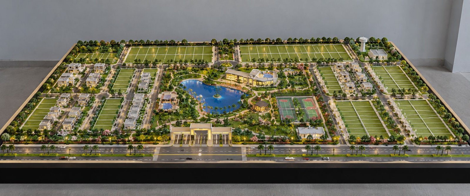
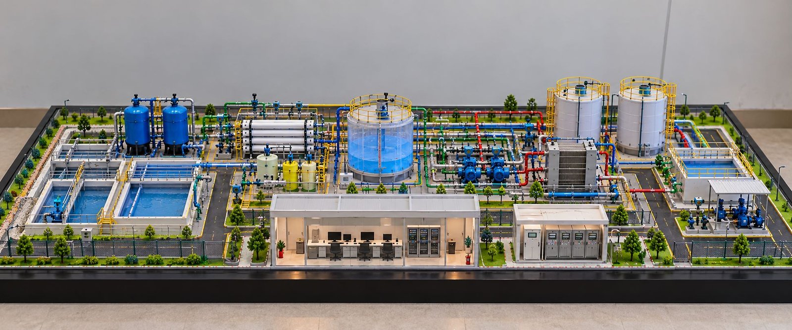
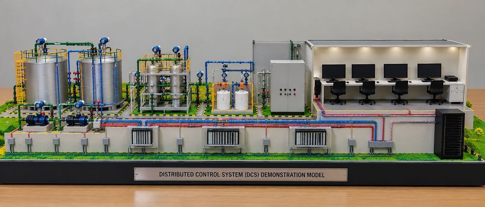
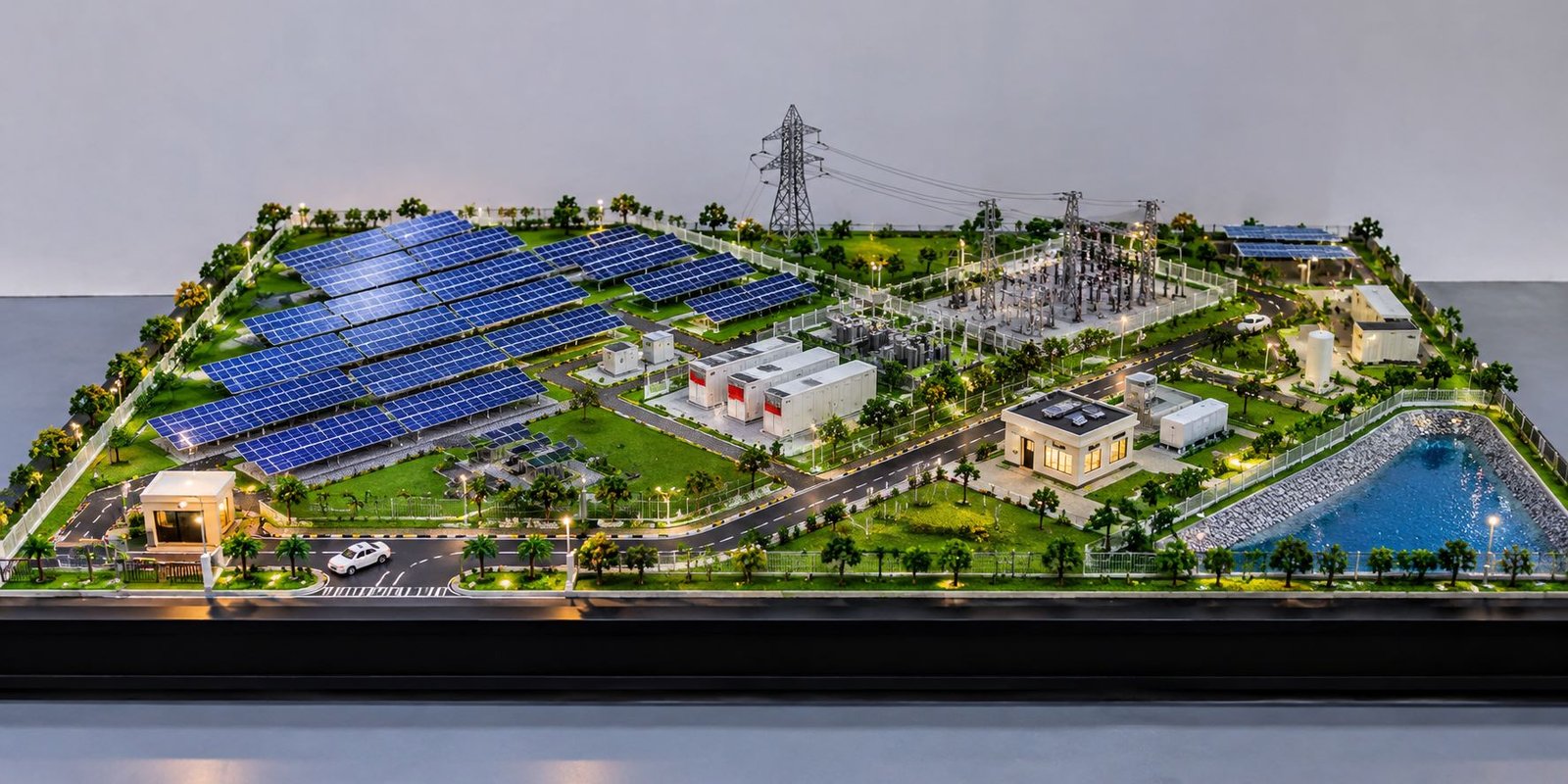
Custom Industrial Plant Model Making for Equipment and Facility Layouts
A Custom Industrial Plant Model provides a detailed three-dimensional representation of an industrial facility, helping engineers, project planners, consultants and technical teams present complex plant layouts in a clear and professional way. These models can include process machinery, interconnected pipelines, pipe racks, storage tanks, cooling systems, utility buildings, internal roads and supporting infrastructure. By bringing these elements together on a physical scale model, viewers can understand the overall facility arrangement more easily than through flat drawings alone.
Industrial projects often involve numerous interconnected systems that must fit within a defined area. Understanding the relationship between machinery, pipelines, structural supports and service areas can be challenging when information is presented only through technical drawings, photographs or digital layouts. A physical model converts this information into a three-dimensional display that can be viewed from different angles during project presentations, planning discussions and engineering reviews.
A Custom Industrial model is developed according to the specific requirements of a project. The quality of the finished display depends on accurate proportions, suitable materials, detailed fabrication and careful finishing. From a compact equipment demonstration to a large industrial facility layout, each model should be designed around the project’s purpose, available drawings and presentation requirements.
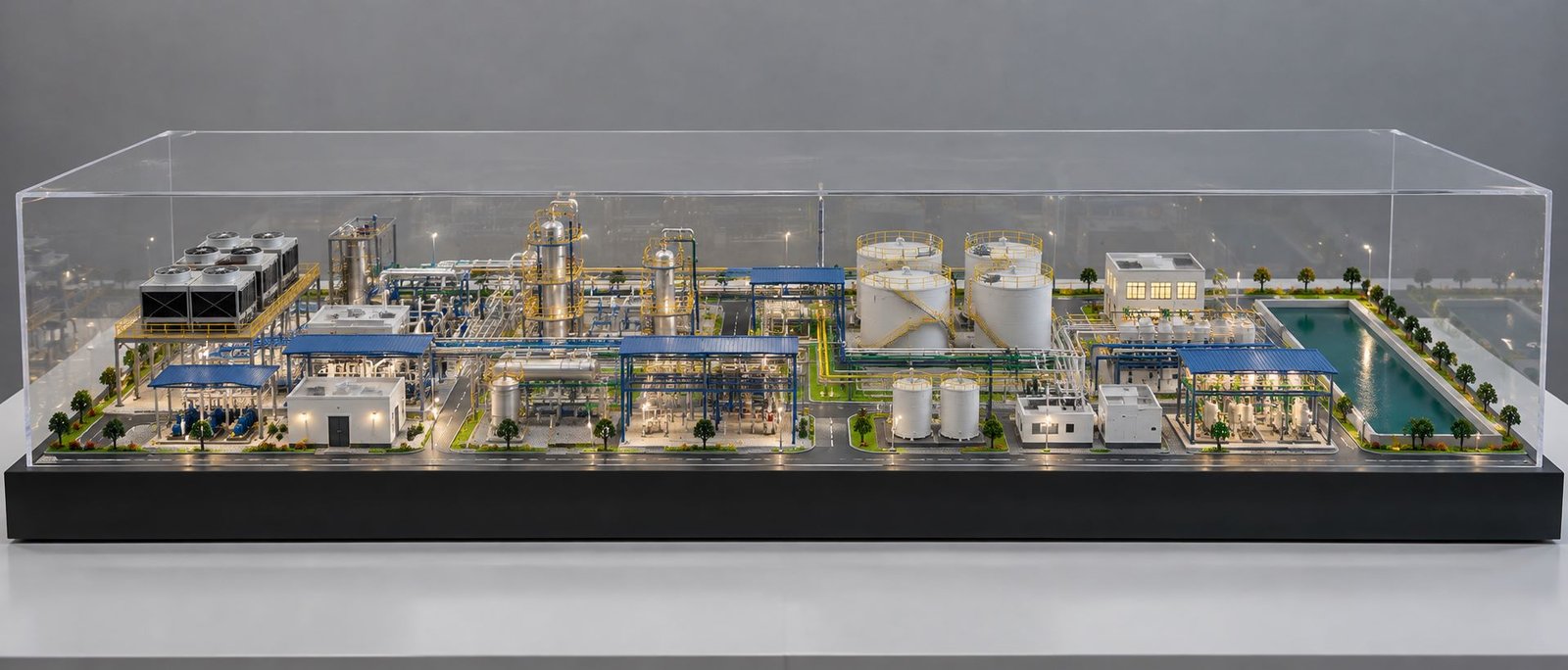
A professionally designed Custom Industrial Plant Model can represent machinery, pipelines, storage tanks, process equipment and supporting infrastructure in a single organised display. The design can be customised according to engineering drawings, equipment dimensions, available space and the intended presentation environment.
What Is a Custom Industrial Plant Model?
A Custom Industrial Plant Model is a scaled physical representation of an industrial facility designed according to project-specific drawings, equipment arrangements and visualisation requirements. Unlike a standard miniature display, a customised model is developed around the layout, machinery, infrastructure and technical features of a particular project.
The model may represent a manufacturing facility, chemical processing plant, power generation unit, refinery, water treatment facility, production line or another industrial installation. Its design depends on the information that needs to be communicated and the level of detail required by the client.
A typical model may include pumps, motors, compressors, heat exchangers, pressure vessels, cylindrical storage tanks, process columns, cooling units, pipe racks and utility buildings. It can also incorporate internal roads, access pathways, platforms, staircases, structural frames and landscaped surroundings where these elements contribute to the overall presentation.
The primary purpose of a Custom Industrial Plant Model is to make an industrial layout easier to understand. Equipment locations become visible, pipeline routes can be followed, and the relationship between different plant sections can be explained through a single physical display.
Importance of Custom Industrial Models for Plant Presentations
Industrial facilities contain multiple components that work together as part of a larger operating system. Their arrangement influences how the facility is presented, how different areas are connected and how the available space is utilised.
A physical scale model helps viewers understand these relationships by displaying the main elements in their relative positions. For example, a process unit can be shown alongside its associated storage tanks, pipelines, access routes and supporting equipment.
This visual representation is particularly useful when a project needs to be explained to people who may not regularly work with engineering drawings. Instead of interpreting multiple plans and elevations separately, viewers can observe the overall facility in three dimensions.
Custom Industrial models can also help teams communicate proposed layouts during meetings, exhibitions, client presentations and project reviews. The model provides a common visual reference for discussing the facility and its major components.
Difference Between Standard and Custom Industrial Models
A standard industrial model usually follows a general design or represents a typical industrial arrangement. A customised model, on the other hand, is developed around the requirements of a specific facility.
A customised design can reflect the position of individual equipment items, the routing of selected pipelines, the dimensions of the display base and the location of buildings and service areas. Components can be fabricated in different sizes and finishes to represent the actual arrangement at the chosen scale.
Customisation also allows the model to focus on particular aspects of a project. An engineering presentation may prioritise piping and machinery, while a facility overview may give more attention to buildings, roads, equipment zones and the overall site layout.
Custom Industrial Plant Models for Machinery and Equipment Layouts
Machinery and process equipment are among the most important features of an industrial facility. Their relative positions help define the overall arrangement of the plant and determine how the different process areas are visually connected.
A Custom Industrial Plant Model can represent major equipment items in a carefully organised layout, allowing viewers to identify individual components and understand their placement within the facility.
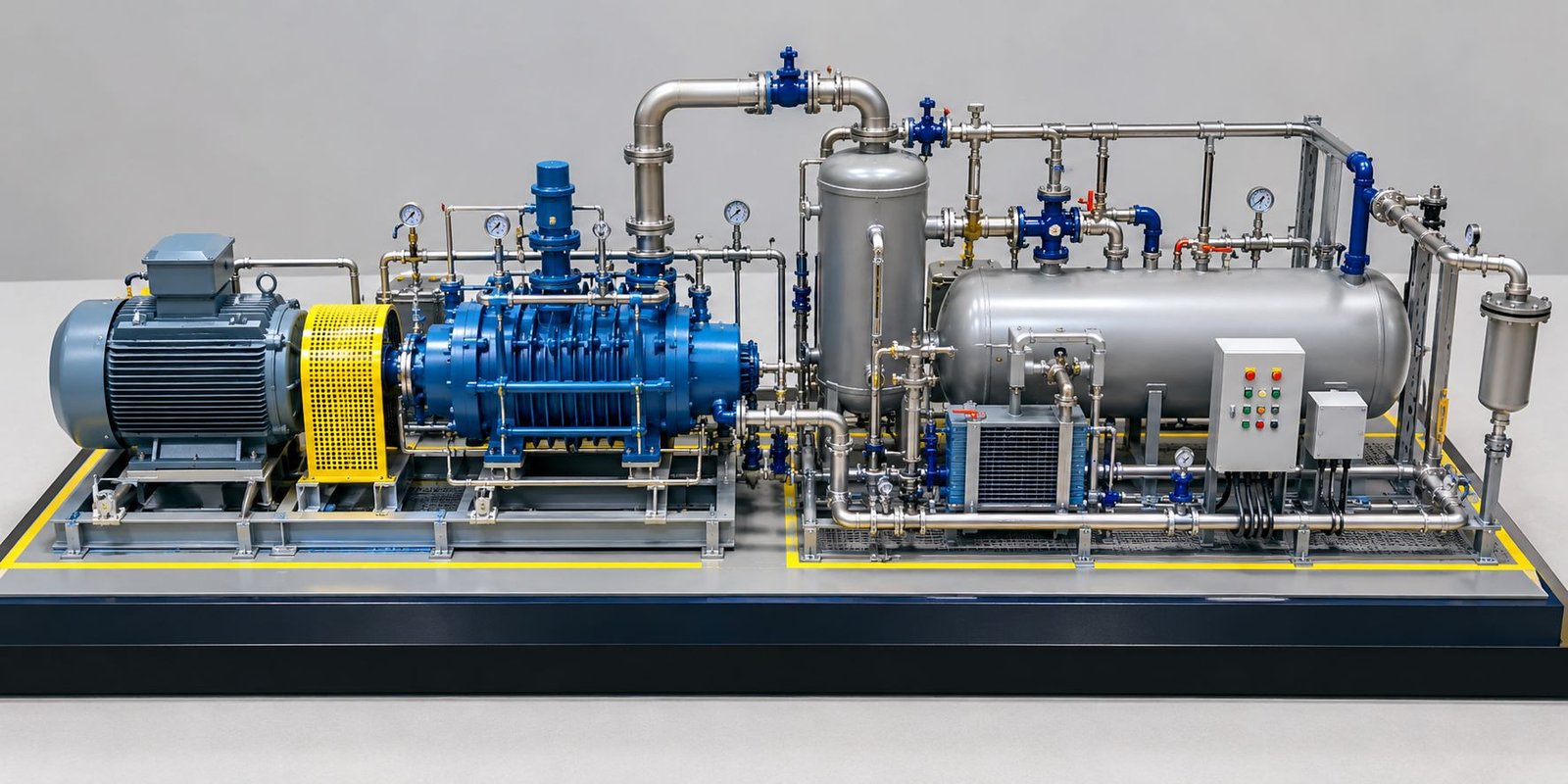
Depending on the project, equipment may include pumps, motors, compressors, pressure vessels, heat exchangers, reactors, filters, cooling units and specialised process machinery. Each component can be fabricated with suitable proportions, colours and surface finishes.
Process Equipment Detailing in Custom Industrial Models
Process equipment often has distinctive shapes and structural features. Cylindrical vessels, rectangular machine housings, vertical columns, horizontal tanks and compact mechanical assemblies can all be represented using suitable fabrication techniques.
The amount of detail should be selected according to the model scale and its intended use. Larger models may accommodate visible flanges, platforms, supports, access ladders and other external features. Smaller models may focus on the overall shape, orientation and position of each equipment item.
A consistent level of detailing helps the finished display look organised and professional. Components should be proportionate to one another, with enough spacing to make the main equipment identifiable without overcrowding the baseboard.
Pumps, Motors and Mechanical Assemblies
Pumps and motors are commonly found in industrial facilities and may be located near storage tanks, process equipment or utility systems. Their positions can be shown clearly in a scale model to communicate the arrangement of mechanical components.
A detailed representation may include the motor housing, pump body, connecting pipes, mounting base and nearby supporting structures. Where several similar units are present, their arrangement can be repeated consistently to maintain the visual accuracy of the model.
These details are especially useful when the display is intended to demonstrate a machinery arrangement or explain the relationship between equipment and associated pipework.
Cooling Systems and Auxiliary Equipment
Cooling units, ventilation systems, electrical equipment and auxiliary machinery contribute to the overall industrial layout. Although these components may not always be the main focus, including them can help create a more complete representation of the facility.
Their position should be coordinated with the major equipment and surrounding structures. Careful placement prevents the model from appearing crowded and makes the overall layout easier to understand.
Custom Industrial Models for Piping and Pipe Rack Systems
Piping systems are a major visual feature of many industrial plants. They connect different process units and carry materials between tanks, machinery and other operating areas. Their routes may pass horizontally, vertically or at different elevations, making them challenging to communicate through a single two-dimensional drawing.
A detailed industrial scale model can represent the main pipeline routes and elevated pipe racks in three dimensions. This makes it easier to understand how different process sections are connected within the facility.
Representation of Industrial Pipelines
Pipelines can be fabricated using suitable small-diameter materials selected according to the model scale and required appearance. The routes can include horizontal sections, vertical risers, bends, connecting branches and visible supports.
The aim is to represent the major routes clearly without making the display unnecessarily complicated. Where a facility contains many pipelines, the model maker may need to prioritise the systems that are most important to the presentation.
Different colours may be used to distinguish selected pipeline groups. The colour scheme should follow the supplied drawings or the client’s presentation requirements rather than introduce unsupported technical meanings.
Elevated Pipe Racks and Structural Supports
Pipe racks provide support for pipelines and are frequently arranged along defined routes through an industrial facility. In a scale model, these structures can be represented using miniature columns, beams, cross-members and horizontal supports.
The height and spacing of the rack should remain consistent with the selected scale. Pipelines should appear properly supported, and the rack should align with the associated equipment and connecting routes.
A well-fabricated pipe rack adds depth to the model and makes the facility look more realistic. It also helps viewers distinguish between equipment installed at ground level and systems arranged above the surrounding plant area.
Pipeline Connections and Equipment Integration
The connection between pipelines and equipment is important for communicating the layout of an industrial plant. A model can show how selected pipes approach tanks, pumps, vessels and other major components.
Visible connections should be positioned carefully to avoid unnecessary overlaps. If several lines meet in a confined area, the design may require careful spacing and a clear colour scheme so that the main routes remain identifiable.
These features can be particularly valuable for presentations in which the piping arrangement is one of the principal subjects.
Custom Industrial Plant Models for Storage Tanks and Process Units
Storage tanks and vessels are commonly used to hold liquids, gases or process materials. Their size, shape and location can have a significant influence on the visual appearance of an industrial facility.
A customised model can include vertical cylindrical tanks, horizontal vessels, process columns and other storage-related components. Their dimensions and relative positions should be based on the available project information and selected model scale.
Cylindrical Storage Tank Models
Cylindrical storage tanks can be represented with suitable body proportions, top surfaces, roofs and supporting details. Depending on the project, the model may include several tanks arranged in a dedicated storage area.
The spacing between tanks should be planned carefully so that the layout remains clear and visually balanced. Connecting pipelines, nearby roads and access areas can be added when they are relevant to the presentation.
For larger models, selected external details can be included to make the tanks more recognisable. Smaller models may use simplified forms while maintaining the correct relative dimensions and placement.
Pressure Vessels and Vertical Columns
Pressure vessels and vertical columns are common features of many process facilities. Their tall or rounded profiles help create visual variation across the model and communicate the arrangement of the process area.
These components can be fabricated with suitable end shapes, supports and external attachments where the scale allows. Their position should be coordinated with nearby machinery, platforms and pipelines.
Process Units and Supporting Structures
Process units may contain several types of equipment arranged within a defined area. A scale model can group these components together while preserving the visible relationships between machinery, support frames and associated pipework.
Platforms, access structures, stairs and service areas may be incorporated where they are necessary to communicate the layout. The level of detail should remain consistent across the entire display.
Custom Industrial Model Materials and Fabrication Methods
Material selection influences the appearance, strength, weight and fabrication possibilities of an industrial model. The appropriate combination depends on the scale, component complexity, budget and final display environment.
A professional model may combine acrylic, plastic sheets, 3D-printed components, laser-cut parts, selected metal elements and suitable finishing materials. Each material should be chosen according to the function of the component and the level of detail required.
Acrylic and Transparent Materials
Acrylic can be used for protective enclosures, transparent panels and selected display features. A clear enclosure allows viewers to observe the model while helping protect delicate components from dust and accidental contact.
The enclosure dimensions should provide sufficient clearance around the model. Its height should accommodate the tallest equipment and structural elements without making the overall display unnecessarily bulky.
Transparent panels should be fitted carefully to maintain a clean appearance and good visibility. The enclosure should also allow practical access for maintenance or cleaning when required.
Plastic Sheets and Fabricated Components
Plastic sheet materials are useful for fabricating equipment housings, platforms, panels, building structures and other miniature components. They can be cut, shaped and assembled according to the required design.
Different thicknesses may be used for different parts of the model. Consistency in cutting, joining and finishing helps create a more refined result.
3D Printing for Complex Equipment
Three-dimensional printing is suitable for components with intricate geometry or shapes that would be difficult to produce using simple sheet fabrication. It can be used for miniature machinery, specialised fittings, complex equipment housings and selected structural details.
Before printing, components should be checked against the intended model scale. Features that are too small may not remain visible after finishing, while oversized details can make the model look disproportionate.
Laser Cutting for Precision Parts
Laser cutting can be used to produce accurate flat components, panels, building parts, platforms and structural elements. It is particularly useful when several similar parts need to be produced with consistent dimensions.
Laser-cut components can be combined with hand-fabricated or 3D-printed parts to create a more detailed model. The final assembly should be checked for alignment, clean edges and consistent proportions.
Finishing, Painting and Colour Coordination
Finishing plays an important role in the overall appearance of an industrial plant model. Surfaces should be clean, colours should be applied consistently and visible joints should be finished carefully.
Equipment, pipe racks, pipelines, buildings and baseboard elements can use different colours to make the layout easier to read. However, colour choices should remain coordinated across the complete model rather than making individual sections appear unrelated.
Custom Industrial Plant Model Baseboard and Acrylic Enclosure
The baseboard provides the foundation for the entire industrial display. It establishes the model boundary, supports the miniature components and helps present the facility as one organised arrangement.
For a wide industrial layout, a broad rectangular baseboard can provide sufficient space for equipment, pipe racks, storage tanks, utility buildings and internal roads. The proportions should reflect the facility layout rather than forcing every project into the same dimensions.
Baseboard Dimensions and Proportions
Baseboard dimensions depend on the footprint of the facility, the selected scale and the available display space. A wide layout may require a longer baseboard, while a more compact plant may fit on a smaller rectangular platform.
The design should maintain suitable spacing around major components and leave enough room for roads, pathways and supporting infrastructure. Important equipment should not be placed too close to the baseboard edges unless the project drawings specifically require that arrangement.
Baseboard Finish and Presentation
The baseboard finish can be selected to complement the model. Dark or neutral finishes may help the equipment, pipelines and miniature structures stand out, while other finishes may be appropriate for specific presentation themes.
The edges should appear straight and clean, and the upper surface should provide a stable foundation for all components. Any labels, identification plates or presentation graphics should be positioned consistently.
Integrating the Baseboard with the Acrylic Enclosure
The acrylic enclosure and baseboard should be planned together. Their dimensions, clearances and overall proportions should complement one another so that the completed display looks balanced.
The enclosure should not obstruct important viewing angles or make the equipment appear cramped. Sufficient clearance should be provided around tall machinery, pipe racks and other prominent components.
Custom Industrial Model Lighting and Visual Presentation Features
Lighting can improve the visibility of selected parts of an industrial model, particularly when it is displayed in a showroom, exhibition or presentation room. However, lighting should be incorporated carefully so that it supports the model rather than distracting from its details.
Internal Model Lighting
Small lighting elements may be used to highlight selected buildings, process areas, pathways or equipment zones. The arrangement should provide balanced illumination without creating excessive glare on the acrylic enclosure.
Wiring and electrical components should be planned during fabrication so that they do not interfere with visible model details. Access for inspection and maintenance should also be considered.
Labels and Identification Panels
Labels can help viewers identify important equipment, plant sections or utility areas. They may be included directly on selected components or placed on suitable identification panels.
The text size should remain readable at the intended viewing distance. Excessive labelling can clutter the display, so the most relevant information should be prioritised.
Colour Coding for Visual Clarity
Colour coding can distinguish different equipment groups and pipeline systems. Consistent colours can also help viewers follow selected routes through the facility.
Any technical colour conventions should be confirmed against the project requirements. When the model is intended mainly for presentation, the colour scheme should be clear, consistent and appropriate to the information being communicated.
Custom Industrial Plant Models for Engineering Presentations
A Custom Industrial Plant Model can help explain a facility’s layout to audiences with different technical backgrounds. By displaying equipment and infrastructure together, the model provides a visual reference that supports discussions about the overall arrangement.
Client and Stakeholder Presentations
During client meetings, a physical model can provide an overview of the proposed facility and its main components. Viewers can examine the layout from different angles and identify the relative positions of important plant sections.
This can make a presentation more engaging and provide a useful reference for explaining the project’s scope. The model should reflect the intended presentation level and include the components that are most relevant to the audience.
Engineering Design Reviews
Engineering teams may use physical models to discuss equipment positioning, structural arrangements and the visual relationship between different systems. The model can make spatial relationships easier to see than they may be in separate drawings.
It is important to distinguish between a presentation model and an engineering verification tool. A physical model can support discussion, but technical decisions must still be based on approved drawings, calculations, specifications and applicable engineering reviews.
Exhibition and Display Applications
Industrial models can be displayed at exhibitions, trade events, project offices and company presentation spaces. A well-finished model allows visitors to understand the facility without requiring a detailed explanation of every drawing.
For exhibition use, durability, transport protection, enclosure quality and ease of viewing should be considered during the design stage.
Training and Equipment Demonstrations
Selected industrial models can also be used as visual aids for training and demonstrations. They can help introduce the arrangement of a facility, show the position of major equipment and explain how different sections are organised.
Where a model is intended for repeated handling or demonstrations, components and attachments should be designed with appropriate durability.
Industrial Plant Model Applications Across Different Industries
Industrial plant models can be adapted for many sectors. The exact components and presentation details depend on the type of facility and the information that needs to be communicated.
Manufacturing and Production Facilities
Manufacturing models can show production machinery, assembly areas, conveyors, material handling equipment, utility rooms and internal circulation routes. The arrangement helps explain how the main production and support areas fit together.
A model can focus on the entire facility or highlight a particular production zone. Equipment groups can be positioned according to the available layout drawings, while selected pathways and access areas provide additional context.
Chemical and Process Industries
Chemical and process facilities may contain reactors, storage tanks, heat exchangers, pumps, vessels, pipe racks and interconnected pipelines. Their complex arrangements can be represented through a detailed three-dimensional model.
The presentation can highlight major process areas and the visible connections between them. Component labels and a consistent colour scheme may help viewers distinguish important systems.
Oil Refineries and Petrochemical Facilities
Refinery and petrochemical models may include process units, tall columns, storage tanks, pipe racks, utility areas and supporting infrastructure. Their varied equipment shapes and elevations create a complex layout that benefits from careful planning.
The model scale should allow the most important components to remain recognisable. If the facility contains a large number of details, the project team should identify which systems need the greatest visual emphasis.
Power Generation Facilities
Power plant models can represent major equipment, auxiliary systems, cooling facilities, service buildings, transformers and other supporting structures. The model can be developed to show the overall facility or a selected equipment area.
The choice of components depends on the plant type and the available drawings. The completed display should maintain consistent proportions and a clear relationship between the main plant areas.
Water and Wastewater Treatment Plants
Water treatment and wastewater treatment facilities often contain tanks, treatment units, pumps, pipelines, control buildings and service areas. A model can show how these elements are distributed across the site.
Where the presentation concerns the facility layout, internal roads, pathways and surrounding infrastructure may also be included. The arrangement should be based on the project’s available plans.
Pharmaceutical and Food Processing Facilities
Pharmaceutical and food processing models may feature production rooms, process vessels, utility equipment, storage areas and service infrastructure. Depending on the project, the model can emphasise the building arrangement or the equipment located within selected areas.
The scope should be established before fabrication, particularly where internal equipment details or multiple building levels are required.
Cement, Steel and Heavy Industrial Facilities
Heavy industrial models can include large machinery, production structures, storage areas, conveyors, processing equipment and supporting buildings. These facilities often require careful scale planning because major components can occupy substantial areas.
A well-organised model can help communicate the relationship between large equipment groups and the surrounding infrastructure.
Custom Industrial Plant Model Fabrication Process
The fabrication process should follow a planned workflow to maintain consistency and reduce avoidable changes. The exact sequence depends on the model’s complexity, available information and presentation requirements.
Review of Drawings and Project Information
The first stage involves reviewing the available general arrangement drawings, equipment layouts, piping layouts, elevations, reference photographs and other relevant information.
This review helps establish which components must be represented, how the facility is arranged and which details need special attention. Missing or conflicting information should be clarified before detailed fabrication begins.
Scale Selection and Overall Planning
The scale determines the relationship between the real facility and the physical model. It affects the overall dimensions, component visibility, level of detail and display requirements.
A smaller scale may be suitable for an overall plant layout, while a larger scale can provide more room for equipment detailing. The chosen scale should balance the available space with the amount of information the model needs to communicate.
Component Design and Fabrication
After the layout is established, individual components can be designed and fabricated. Different methods may be used for equipment bodies, tanks, pipe racks, buildings, platforms and structural supports.
The fabrication method should suit the shape and size of each component. Repeated parts should be produced consistently, while specialised equipment may require individual modelling or custom fabrication.
Assembly and Pipeline Installation
The fabricated components are positioned on the baseboard according to the approved layout. Major equipment is placed with reference to the overall arrangement so that the relationship between machinery, tanks and supporting structures remains consistent.
Pipelines, pipe racks and smaller components are then integrated into the layout as required. Careful alignment helps maintain a clear presentation and prevents important features from being obscured.
Painting and Final Finishing
Once the components are assembled, finishing work helps create a consistent appearance. This may include painting, surface preparation, edge finishing, cleaning and the installation of selected labels or lighting elements.
The model should be inspected for visible gaps, uneven finishes, misplaced components and unnecessary obstructions. Any required corrections should be completed before the display is prepared for delivery.
Protective Enclosure and Quality Review
If the model requires an acrylic enclosure, the enclosure should be checked for proper fit, visibility and clearance around the tallest components. The baseboard, enclosure and model should form a balanced display.
The final review should confirm that the main equipment, pipelines, storage tanks and other requested features are present and positioned appropriately. Transport and handling requirements should also be considered before the completed model is packed.
Custom Industrial Plant Model Cost and Design Considerations
The cost of an industrial plant model depends on its size, complexity, materials, detailing and presentation requirements. Because each project has different needs, an accurate estimate requires a clear understanding of the intended scope.
Overall Model Size and Scale
Larger models generally require more material, fabrication time and assembly work. The scale also influences the size of individual components and the amount of detail that can be included.
A smaller model may be more economical, but it may not provide enough space to show intricate machinery or complex piping arrangements clearly. The appropriate scale should be selected according to the intended use rather than size alone.
Number and Complexity of Components
A model with a few major equipment items will usually require less fabrication than one containing numerous machines, storage tanks, pipe racks and structural details.
Complex shapes, repeated small components and closely spaced pipeline systems may require additional design and assembly time. Identifying the essential features at the beginning helps keep the scope manageable.
Materials and Fabrication Methods
Material costs vary according to the type and quantity of materials required. Specialised 3D-printed parts, precision-cut components, selected metal structures and transparent enclosures can affect the overall estimate.
The fabrication method should be chosen according to the model’s requirements, with attention to durability, appearance and component accuracy.
Lighting, Enclosures and Additional Features
Lighting, identification labels, removable sections, transparent enclosures and customised display bases may add to the fabrication requirements.
These features should be discussed before work begins so they can be incorporated into the design and budget. Adding them later may require changes to the baseboard, internal wiring or component arrangement.
Project Information and Delivery Requirements
Complete drawings and reference material can make the planning process more straightforward. Incomplete information may require additional clarification or design work.
The delivery schedule, packaging requirements and transport arrangements can also affect the overall project cost. A clearly defined scope provides a better basis for preparing a quotation.
How to Choose the Right Industrial Model Making Company
Choosing a model-making provider is an important part of achieving a professional result. The provider should be able to understand the project’s requirements, work with the available engineering information and fabricate the necessary components to a consistent standard.
Review Relevant Industrial Model Experience
Look for examples of industrial models featuring machinery, pipelines, tanks, pipe racks and other components similar to those required for your project.
Reviewing relevant work can help you assess component proportions, surface finishing, layout clarity and the overall quality of the display. A provider’s experience with complex equipment layouts may be particularly valuable for projects involving many interconnected systems.
Confirm the Ability to Work from Technical Drawings
The model-making process often relies on general arrangement drawings, equipment layouts, elevations and reference images. Confirm that the provider can review these materials and identify any information needed before fabrication begins.
Clear communication about dimensions, scale and the level of detail helps ensure that the final model matches the intended presentation.
Discuss Materials and Finishing Quality
Ask which materials and fabrication techniques are appropriate for the proposed model. The choice should reflect the component shapes, required detail, budget and expected display environment.
Finishing quality is equally important. Clean joints, consistent colours, well-aligned components and a properly finished baseboard contribute to a professional result.
Confirm the Project Scope and Delivery Schedule
Before fabrication begins, agree on the main components, overall dimensions, scale, enclosure requirements, lighting and expected delivery schedule.
A clearly defined scope helps establish realistic expectations and reduces the risk of misunderstanding. Any changes to the approved design should be reviewed for their impact on fabrication time and cost.
Common Challenges in Custom Industrial Plant Model Making
Industrial models can be challenging because they often combine numerous components within a limited display area. Careful planning helps address these issues before they affect the finished presentation.
Managing Dense Equipment Arrangements
Industrial layouts may contain machinery, tanks, buildings and service areas positioned close together. If the model is too crowded, individual components may become difficult to identify.
The layout should be reviewed at the selected scale to confirm that the important elements remain visible. Where necessary, the presentation scope can be adjusted to prioritise the most relevant equipment.
Representing Complex Pipeline Routes
Multiple pipelines may cross, change elevation or connect different equipment groups. Representing every line in a small model can reduce visibility and make the display difficult to interpret.
The most important routes should be identified in advance. Consistent spacing, suitable colours and carefully positioned pipe supports can improve visual clarity.
Maintaining Proportions and Alignment
Inconsistent component sizes can make a model appear unrealistic. Equipment, structures and pipelines should be developed according to the same selected scale wherever practical.
Regular checks during assembly help ensure that components remain aligned and that the finished layout reflects the approved arrangement.
Protecting Delicate Components
Small pipelines, supports, railings and other miniature details can be vulnerable during handling and transport. The model should be assembled and packed with suitable protection for delicate parts.
Where a protective enclosure is required, it should be planned as part of the overall design rather than treated as an afterthought.
Future Trends in Custom Industrial Scale Model Making
Industrial model making continues to benefit from developments in digital design and fabrication. These techniques can improve the preparation of complex components and make it easier to adapt a model to project-specific requirements.
Integration of CAD and 3D Design
Computer-aided design can help establish dimensions, component positions and the overall model layout before physical fabrication. Digital planning can also help identify potential fit and spacing issues at an early stage.
Where suitable digital files are available, they may support the production of selected components. However, the quality of the final model still depends on careful fabrication, assembly and finishing.
Greater Use of 3D Printing
3D printing makes it possible to create detailed miniature equipment, unusual geometries and specialised components. It can be particularly useful when a project includes parts that are difficult to produce through conventional fabrication.
The process should be selected according to the required finish, dimensions and durability. Printed parts may still need sanding, painting or other finishing work to match the rest of the model.
Improved Visualisation and Presentation
Industrial models can be designed with improved lighting, transparent protective enclosures and clearly organised display layouts. These features help viewers focus on the most important parts of the facility.
Some projects may also combine a physical model with digital presentations, drawings or explanatory graphics. The combination can provide additional context while keeping the physical model as the central visual reference.
Preparing Your Requirements for a Custom Industrial Plant Model
A clear project brief helps the model-making team understand what needs to be represented and how the finished display will be used. It also supports more accurate planning and quotation.
Before requesting a proposal, prepare the available general arrangement drawings, equipment layouts, piping drawings, reference images and any other relevant project information.
It is helpful to specify the approximate model dimensions, preferred scale, important equipment items, required pipeline details, baseboard finish and whether an acrylic enclosure or lighting is needed. The intended use should also be explained, such as a client presentation, engineering review, exhibition display or facility overview.
If the complete facility contains more detail than can be shown clearly at the selected scale, identify the priority components. This allows the model design to focus on the most important visual information while maintaining a balanced overall layout.
A well-defined brief makes it easier to agree on the scope, materials, finishing requirements, cost and delivery expectations before fabrication starts.
Conclusion
A Custom Industrial Plant Model provides a clear three-dimensional representation of complex industrial facilities. By combining process machinery, piping systems, pipe racks, storage tanks, cooling equipment, utility buildings and supporting infrastructure, it helps engineers and project teams communicate the overall layout more effectively.
The success of a Custom Industrial model depends on careful scale selection, appropriate materials, accurate component placement and consistent finishing. A well-planned rectangular baseboard and a suitable acrylic enclosure can further improve the presentation and protect delicate details.
Whether the project involves a manufacturing facility, refinery, power plant, process installation or water treatment facility, the model should be developed according to the available drawings and the intended presentation purpose. With a clearly defined scope and a structured fabrication process, a custom industrial scale model can become a valuable visual aid for project communication and stakeholder presentations.