Renewable Energy Engineering Model Making: Detailed Coastal Energy Project
Introduction to Renewable Energy Engineering Model Making
Renewable Energy Engineering Model Making helps engineers present complex renewable energy projects through detailed physical scale models. These models combine wind turbines, solar panels, electrical substations, transmission towers, roads, and coastal landscapes in one realistic display. They help viewers understand how renewable energy equipment and supporting infrastructure work together. Moreover, a well-designed physical model makes technical concepts easier to explain during engineering presentations, exhibitions, and project discussions.
Renewable energy plays an important role in modern infrastructure development. Solar power plants, wind farms, and electrical transmission networks support the growing demand for electricity. However, large energy projects often involve several interconnected systems that can be difficult to understand through drawings alone. A physical engineering model presents these systems in three dimensions and provides a clear view of their arrangement.
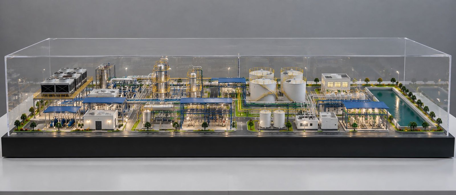
The coastal renewable energy model discussed in this article features a large blue water body, miniature wind turbines, ground-mounted solar panel arrays, a floating solar concept, an electrical substation, transmission towers, internal roads, landscaping, and a transparent protective enclosure. Each component represents a different part of the overall energy landscape.
The model uses a wide rectangular base with a relatively low overall profile. This layout provides sufficient space for the major installations while allowing viewers to examine the complete project from a broad viewing angle. In addition, the combination of blue water, sandy terrain, green vegetation, and detailed electrical equipment creates a realistic physical presentation.
Renewable Energy Engineering Model Making and Project Overview
A renewable energy engineering scale model represents a renewable energy facility or an integrated power project in miniature form. It reproduces important structures at a reduced scale while maintaining their visual relationships and overall arrangement.
Depending on the project requirements, a model may include wind turbines, solar panels, electrical substations, transmission towers, service roads, water bodies, maintenance areas, and landscaped zones. Consequently, viewers can understand how different installations occupy the site and connect with the supporting infrastructure.
The coastal model brings renewable energy equipment and landscape features together within one rectangular display area. Instead of showing a single machine, it communicates the broader layout of an energy development. Viewers can identify the wind turbine locations, examine the solar panel arrays, locate the substation, and observe the relationship between land and water.
Furthermore, a physical model provides a useful visual reference during technical meetings. Engineers can present it alongside site plans, equipment drawings, diagrams, and digital visualisations. Although a conceptual model helps explain the overall design, an engineering review model requires verified dimensions, technical drawings, and project-specific information.
Renewable Energy Engineering Model Making and Site Detailing
The model uses a long rectangular base to accommodate several energy systems and landscape features. A large blue water body occupies a prominent section, while the surrounding land contains wind turbines, solar installations, electrical equipment, roads, and miniature vegetation.
The layout creates distinct zones without making the project look disconnected. For example, the solar panels occupy organised sections of land, while the wind turbines stand across the sandy terrain. Meanwhile, the electrical substation sits inside a defined compound near the transmission infrastructure.
A paved road runs along the front edge of the model. This road establishes a clear boundary and gives the miniature landscape a planned appearance. Rows of trees and green patches also define selected parts of the site perimeter.
The transparent enclosure protects delicate miniature components from dust and accidental contact. At the same time, it allows viewers to inspect the model from different angles. Beneath the landscape, the rectangular base provides structural support and a consistent outer boundary.
The wide layout makes the model suitable for displaying several connected systems together. As a result, viewers can understand the relationship between renewable energy generation, electrical distribution, site accessibility, and the surrounding environment in one view.
Renewable Energy Engineering Model Making for Wind Turbines
Wind turbines form one of the most recognisable features of the model. Several white miniature turbines stand across the coastal landscape and represent a wind energy installation.
Wind Turbine Design and Detailing
Each wind turbine features a tall tower, a nacelle, and a three-bladed rotor. The white finish creates a clear contrast against the sandy ground, blue water, and green vegetation.
The proportions of these components strongly influence the model’s realism. Therefore, the fabricator must maintain consistent tower dimensions, rotor sizes, and blade alignment. Careful assembly also helps the turbines look like coordinated engineering structures.
The rotor blades require particular attention because viewers can see them clearly even from a distance. Similarly, the tower height must match the selected scale so that the turbines fit naturally within the overall landscape.
Wind Farm Layout and Turbine Distribution
The model distributes the turbines across different sections of the land. This arrangement communicates the extent of the proposed wind installation instead of presenting the turbines as isolated objects.
In an actual wind farm, engineers select turbine locations according to wind conditions, terrain, foundation requirements, environmental restrictions, and equipment specifications. They also consider turbine spacing and site constraints.
A project-specific model can reproduce the intended turbine positions using the supplied site plan. In addition, the fabricator can adjust the number, height, and spacing of the turbines to match the proposed development.
Integration with Supporting Infrastructure
The turbines stand alongside roads, electrical facilities, and landscaped areas. This arrangement helps viewers understand how wind generation equipment fits into a larger infrastructure project.
Depending on the design, a detailed model can also include turbine foundations, maintenance tracks, cable routes, and associated electrical equipment. These features provide a more complete representation of the installation.
Consequently, the wind turbine section communicates both the appearance of the equipment and its place within the overall energy development.
Renewable Energy Engineering Model Making for Solar Panels
The model features groups of dark blue solar panels arranged in organised rows across the land. These rectangular modules represent ground-mounted photovoltaic installations.
Solar Panel Array Design and Detailing
The solar panels form repeated patterns that give the installation a realistic engineering appearance. Their dark blue surfaces contrast with the green landscape and sandy terrain, making the solar zones easy to identify.
A physical model can reproduce these panels using thin acrylic sheets, laser-cut components, printed surfaces, or other suitable materials. Furthermore, miniature mounting structures can improve the appearance by showing how the panels sit above the ground.
The panel dimensions, row spacing, orientation, and overall arrangement can follow the supplied project drawings. This approach helps maintain a consistent relationship between the solar installation and the surrounding infrastructure.
Ground-Mounted Solar Power Plant Model
The model places the solar arrays within defined sections rather than scattering them across the site. Therefore, viewers can distinguish the photovoltaic installation from the wind energy area and the electrical substation.
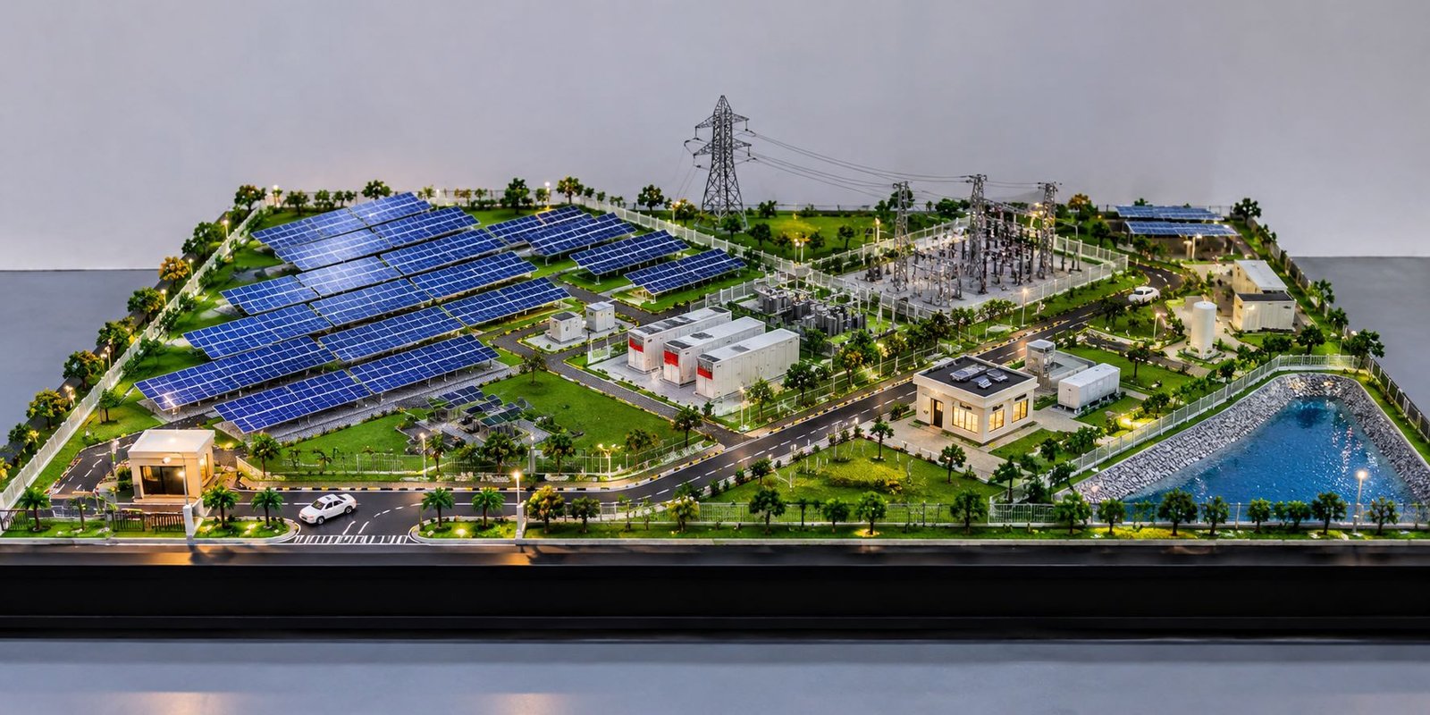
A more detailed solar power plant model may also include inverter stations, transformer units, maintenance paths, cable routes, access roads, fencing, and control buildings.
These components explain how a solar power plant operates as an integrated system. Solar panels generate electricity, while associated electrical equipment manages the output and supports its connection to the wider network.
Importance of Solar Panel Detailing
Repeated components require consistent dimensions and alignment. Even small variations can become noticeable when the model contains many rows of panels.
For this reason, accurate spacing, uniform colouring, and clean assembly contribute significantly to the final presentation. In addition, clearly defined access routes help viewers understand how maintenance teams can reach different sections of the installation.
Renewable Energy Engineering Model Making for Floating Solar
The model includes light-coloured rectangular elements on the water surface that visually suggest a floating solar installation. Floating photovoltaic systems support solar panels on suitable water bodies using specially designed floating structures.
Engineers consider anchoring, electrical connections, water conditions, maintenance access, and environmental requirements when developing these installations. A physical model can communicate the general concept and show how the proposed arrangement relates to nearby infrastructure.
Floating Solar Platform Model Design
A floating solar model can represent groups of panels arranged on miniature floating platforms. Repeated modules help communicate the layout and scale of the proposed installation.
For greater detail, the fabricator can add connecting walkways, access points, electrical routes, and anchoring representations where the project design requires them. Moreover, consistent module spacing helps viewers distinguish the floating installation from the ground-mounted solar arrays.
Relationship Between Water and Solar Generation
The floating solar concept introduces an alternative location for photovoltaic equipment. Instead of occupying only land, the installation uses part of the water surface.
This arrangement allows viewers to compare two types of solar installations within one physical model. The ground-mounted panels occupy the surrounding land, while the floating solar elements appear on the blue water body.
However, the depicted arrangement should be treated as a conceptual representation unless verified project drawings confirm the technical design. Actual implementation requires suitable engineering studies and project-specific specifications.
Renewable Energy Engineering Model Making for Coastal Water and Shoreline
The blue water body forms a major visual feature of the model. It extends across a substantial portion of the base and creates a clear separation between the water and the surrounding land.
Water Surface and Colour Treatment
The model uses shades of blue to create visual depth across the water surface. Lighter details follow parts of the shoreline and selected internal features, adding variation to the surface.
A fabricator can reproduce water using painted boards, acrylic sheets, textured coatings, or suitable resin finishes. The best option depends on the model’s scale, budget, and required appearance.
A clean finish helps the water surface look realistic without distracting viewers from the engineering equipment. In addition, carefully controlled colour variation creates a better visual transition between the shoreline and the surrounding terrain.
Shoreline Shape and Terrain Transition
The shoreline follows an irregular outline rather than a simple straight boundary. This shape gives the model a more natural coastal appearance.
The surrounding terrain uses sandy brown and beige colours, which contrast with the blue water. Consequently, viewers can easily distinguish the land from the water body.
For a project-specific model, the fabricator can develop the shoreline from the site plan or geographical information. This method helps maintain consistency between the physical representation and the intended project layout.
Coastal Infrastructure Planning
Coastal renewable energy projects may require access routes, maintenance areas, electrical connections, cable corridors, and supporting facilities.
A physical model can show how these elements relate to the shoreline. For example, the design may include service routes, access platforms, protective structures, or designated maintenance areas.
The exact features should follow the project drawings. This ensures that the model communicates the intended infrastructure instead of introducing unsupported design details.
Renewable Energy Engineering Model Making for Electrical Substations
The model includes an electrical substation within a designated compound. Numerous miniature structures appear in organised rows, creating the appearance of an electrical installation with multiple equipment sections.
The substation represents an important connection between renewable energy generation and the wider power network.
Electrical Substation Equipment and Layout
The compound contains repeated electrical structures and connecting elements. Their organised placement creates a technical appearance and distinguishes the substation from the surrounding landscape.
Depending on the actual design, a customised model can include transformers, circuit breakers, isolators, busbars, current transformers, voltage transformers, protective equipment, cable trenches, and control buildings.
The fabricator can produce these miniature components using plastic profiles, acrylic, metal sections, precision-cut parts, or 3D-printed pieces. Careful spacing and consistent dimensions help maintain a clear equipment layout.
Compound Boundaries and Internal Layout
The substation occupies a defined area, which separates the electrical equipment from the nearby roads and landscaped zones.
A detailed model may also include perimeter fencing, access gates, internal roads, equipment foundations, control rooms, and miniature lighting poles. These features help explain how engineers organise the facility and create a more complete visual representation.
Role of the Substation in Renewable Energy Projects
Wind turbines and solar panels generate electricity, but the project also requires equipment to manage and connect the output to the intended network.
Depending on its design, an electrical substation can perform voltage transformation, switching, protection, and other electrical functions.
Including a substation in the model helps viewers understand the relationship between generation facilities and supporting electrical infrastructure. Therefore, the substation contributes both technical detail and visual importance to the overall presentation.
Renewable Energy Engineering Model Making for Transmission Towers
The model features miniature lattice-style transmission towers near the electrical substation. These structures represent infrastructure that can support the transmission of electricity across a project area.
Transmission Tower Scale Model Design
A typical lattice tower uses a framework of structural members to support electrical conductors at specified clearances.
In a physical model, the fabricator can reproduce this framework using fine wire, miniature metal profiles, plastic sections, or 3D-printed components. Cross-arms and tower legs help establish the familiar appearance of the structure.
The dimensions and arrangement should reflect the selected tower type. In addition, the component thickness must suit the scale so that the structure appears realistic rather than oversized.
Tower Positioning and Grid Connectivity
The position of the transmission towers helps establish a visual connection between the substation and the wider electrical network.
For a project-specific model, the fabricator can follow the supplied layout to position the towers and represent the intended connection route. Fine wires may represent the conductors where appropriate.
This arrangement helps explain how electrical infrastructure connects different parts of the project. However, the actual route and connection design must follow the relevant engineering documentation.
Renewable Energy Engineering Model Making for Roads and Landscaping
The model includes paved roads, miniature trees, green patches, sandy terrain, and clearly defined infrastructure zones. These features organise the landscape and improve the presentation of the renewable energy installations.
Internal Roads and Site Accessibility
The model includes paved roads along the front edge and connecting routes within the landscape. These roads establish a clear circulation pattern between different infrastructure zones.
The roads use contrasting surface colours and defined edges to distinguish them from the surrounding terrain. Their alignment also separates selected parts of the site.
A customised model can include road junctions, turning areas, access gates, service routes, and other circulation features according to the project layout.
Maintenance and Operational Access
Wind turbines, solar installations, substations, and associated facilities require suitable access for inspection, maintenance, and equipment delivery.
The model can show how roads connect the different installations. This arrangement helps project teams discuss the site’s organisation and identify the intended access points.
Depending on the design, additional features may include maintenance tracks, pedestrian paths, service platforms, or designated equipment access areas.
Vegetation and Green Boundaries
Rows of miniature trees define parts of the boundary and add depth to the landscape. Green areas also soften the appearance of the electrical infrastructure and solar installations.
For a customised project, the fabricator can select vegetation according to the intended environment. A coastal development may require a different landscaping treatment from an inland solar plant or an industrial wind farm.
Sandy Terrain and Ground Texture
The sandy terrain is especially visible around the wind turbines. Beige and brown tones create contrast with the water, vegetation, and paved roads.
A fabricator can use textured paint, fine sand coatings, sculpted surfaces, or other suitable materials to reproduce the required ground finish.
The texture should remain proportional to the scale. Excessively coarse materials can make a miniature landscape look unrealistic, whereas a consistent finish improves the overall appearance.
Renewable Energy Engineering Model Making: Lighting and Visual Presentation
Small illuminated points appear around selected roads and site boundaries. These details suggest miniature outdoor lighting and enhance the model’s exhibition appearance.
Miniature LED Lighting
LEDs can represent streetlights, perimeter lighting, selected buildings, and other illuminated features.
The fabricator should plan the lighting system before assembly. This allows the team to conceal wiring and power connections within the base wherever practical.
The lighting arrangement should highlight important features without distracting viewers from the main engineering components. Therefore, the number and position of the lights require careful planning.
Lighting for Exhibition and Photography
Balanced illumination makes the turbine structures, solar arrays, substation equipment, and landscape details easier to see.
For exhibition purposes, controlled lighting can draw attention to important areas while preserving the natural colours of the model.
Similarly, suitable studio lighting helps produce clear feature images. A wide camera angle reveals the overall layout, while reduced reflections keep the miniature details visible through the transparent enclosure.
Renewable Energy Engineering Model Making: Baseboard and Enclosure
The transparent enclosure and rectangular base give the model a finished display appearance. Together, these elements support the miniature landscape and help protect delicate components.
Protective Transparent Enclosure
A clear acrylic enclosure can protect the model from dust and accidental contact. It also allows viewers to examine the miniature installation from different angles.
The enclosure must provide sufficient clearance above the tallest wind turbine and around the landscape. In addition, the fabricator should consider material thickness, support arrangements, access requirements, and transportation needs.
A clean, transparent surface improves visibility and creates a professional presentation.
Rectangular Baseboard Construction
The baseboard supports the water surface, terrain, turbines, solar panels, electrical substation, roads, and landscaping.
Depending on the dimensions and weight, the fabricator may use MDF, plywood, acrylic, or another suitable substrate.
The front edge should have a consistent finish, and the visible border should remain even wherever possible. The base must also provide sufficient rigidity to support the miniature structures during display and transportation.
The wide rectangular format allows the model to present several connected systems together. Consequently, it works well for infrastructure exhibitions, technical presentations, and project displays.
Materials Used in Renewable Energy Engineering Model Making
The fabrication process depends on the model’s dimensions, complexity, durability requirements, and intended use. A combination of materials and techniques can help achieve a realistic physical finish.
Acrylic and Laser-Cut Components
Acrylic sheets can represent transparent enclosures, selected structural components, and smooth water surfaces. Laser cutting helps produce accurate and repeatable shapes.
For example, the fabricator can use laser-cut components for miniature panels, building elements, and selected equipment parts. Consistent dimensions improve alignment during assembly.
3D Printing for Custom Components
Three-dimensional printing can produce customised turbine components, equipment housings, miniature structural parts, and complex shapes.
This method becomes particularly useful when standard miniature components do not match the project requirements. It also allows the fabricator to reproduce selected details from digital designs.
Hand Fabrication and Assembly
Fine wire, plastic profiles, metal sections, and other modelling materials can represent transmission towers, railings, miniature supports, and infrastructure components.
Careful assembly is essential because small alignment errors become noticeable when the model contains many repeated parts.
Surface Finishing and Quality Control
Painting, texturing, and colour coordination give the model a consistent appearance. Blue water, sandy terrain, green vegetation, grey roads, white wind turbines, and dark solar panels help distinguish the different systems.
Before completing the model, the fabricator should check alignment, loose components, uneven paintwork, exposed wiring, inconsistent edges, and visible adhesive marks.
These checks improve the final finish and help maintain a clear engineering presentation.
Applications of Renewable Energy Engineering Scale Models
Engineering Project Presentations
Developers and consultants can use physical models to explain the layout of proposed renewable energy facilities. A three-dimensional display complements site plans, engineering drawings, and digital presentations.
Moreover, the model allows viewers to examine the spatial relationships between different components from several angles.
Infrastructure Planning Discussions
Engineering teams can use a model to review the arrangement of wind turbines, solar installations, electrical substations, roads, and supporting infrastructure.
A conceptual model supports visual communication. However, detailed engineering reviews still require verified drawings, calculations, and technical specifications.
Trade Exhibitions and Corporate Displays
Renewable energy companies can display scale models at exhibitions, conferences, offices, and project presentations.
The wide format allows visitors to view the overall project in one glance. Meanwhile, the miniature components encourage closer inspection of the engineering details.
Educational and Training Purposes
Engineering colleges and technical institutions can use renewable energy models to explain wind turbines, photovoltaic panels, substations, transmission systems, and infrastructure planning.
For example, instructors can use the model to discuss the relationship between electricity generation and supporting distribution facilities. As a result, students can visualise the overall arrangement more easily.
Client and Stakeholder Communication
A physical model can help communicate a proposed development to clients, investors, project teams, and other stakeholders.
It provides a visual reference for discussing the site layout and major infrastructure components. Nevertheless, the model does not replace engineering calculations, environmental assessments, financial analysis, or detailed design documentation.
Custom Renewable Energy Scale Model Making
Fabricators can customise renewable energy engineering models according to individual project requirements.
The overall dimensions and scale can match the available display area. Similarly, the positions of wind turbines, solar panels, substations, transmission towers, roads, water bodies, and landscaped zones can follow the supplied site layout.
Material selection can reflect the required appearance and durability. For instance, acrylic, laser-cut components, 3D-printed parts, and hand-fabricated structures can work together in a single model.
The design can also include miniature lighting and a transparent protective enclosure. These features help highlight the main installations and protect the model during display.
For greater technical accuracy, the fabrication process should use suitable site plans, equipment drawings, dimensions, and project documentation. This approach helps maintain consistency between the physical model and the intended engineering design.
Conclusion: Renewable Energy Engineering Model Making
Renewable Energy Engineering Model Making provides an effective way to present renewable energy installations and their supporting infrastructure in a three-dimensional format.
The coastal renewable energy model discussed in this article combines wind turbines, ground-mounted solar arrays, a floating solar concept, a large blue water body, an electrical substation, transmission towers, internal roads, landscaping, lighting, and a transparent enclosure.
Each component contributes to the representation of an integrated energy landscape. The wide rectangular base accommodates several systems, while the relatively low profile makes the model suitable for exhibitions, engineering presentations, educational demonstrations, and project discussions.
A well-fabricated physical model makes complex infrastructure easier to understand because it shows how different facilities fit together within one development. Ultimately, suitable project information, consistent proportions, careful material selection, and clean finishing help create a clear and useful engineering presentation.