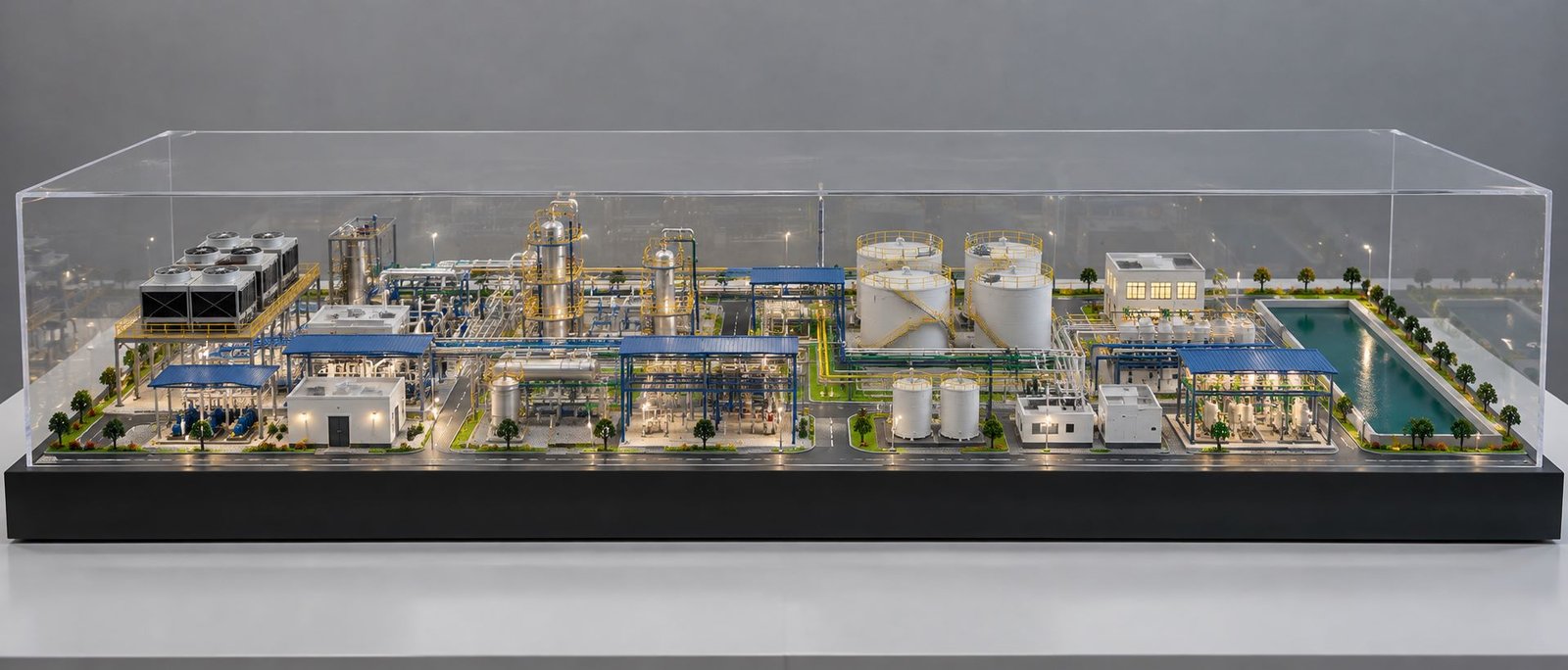
DG Set Engineering Model: Detailed Diesel Generator Scale Model Making
Introduction to DG Set Engineering Models
A DG Set Engineering Model shows the design and arrangement of a diesel generator in a smaller physical form. DG stands for Diesel Generator. This system uses a diesel engine to drive an alternator and generate electricity. Many industries use diesel generators to supply backup power during electricity failures. For example, hospitals, factories, commercial buildings, data centers, construction sites, and infrastructure projects often depend on DG sets for reliable power.
A detailed DG set scale model helps engineers, architects, equipment manufacturers, and project managers understand the complete generator assembly. It shows how different mechanical and electrical components work together. Moreover, it allows viewers to examine the engine, alternator, radiator, exhaust system, fuel connections, battery arrangement, control panel, and supporting frame in one presentation.
Professional engineering model making requires more than a good appearance. The model maker must understand the equipment layout, component proportions, connection points, and fabrication methods. Therefore, accurate reference drawings and proper planning play an important role in the final result.
A diesel generator model can represent an open-type DG set, a soundproof generator, or a containerized power generation system. The design depends on the actual equipment, available drawings, project requirements, and intended use.
Companies can use these models for industrial exhibitions, technical presentations, equipment demonstrations, engineering education, and project visualization. With accurate detailing and professional finishing, a DG set engineering model can communicate complex technical information in a clear and practical way.
What Is a Diesel Generator Set?
A diesel generator set converts the energy stored in diesel fuel into electrical energy. It uses a diesel engine to produce mechanical rotation, while an alternator converts that rotation into electricity.
The engine and alternator form the main parts of the generator. However, the complete system also requires several supporting components. These include a cooling system, lubrication system, fuel supply, air intake, exhaust arrangement, starting battery, control panel, and structural base frame.
Each component performs a specific function. The fuel system supplies diesel to the engine, while the air intake system provides air for combustion. After combustion, the engine produces mechanical power and drives the alternator. Meanwhile, the cooling system controls engine temperature, and the exhaust system carries combustion gases away from the engine.
A well-designed DG set engineering model represents these parts in their correct positions. It also shows their relationship with the main assembly.
For industrial model making, the designer should study the actual generator configuration before developing the miniature. Different manufacturers use different engine layouts, radiator arrangements, exhaust systems, and control panels. Consequently, the model should follow the selected reference rather than use a generic arrangement for every project.
Major Components of a DG Set Engineering Model
Diesel Engine
The diesel engine acts as the main power source of a DG set. It burns diesel fuel inside its cylinders and produces the force required to rotate the crankshaft. The crankshaft then transfers mechanical power to the alternator through a suitable coupling arrangement.
A realistic diesel generator scale model should show the main engine block, cylinder head area, rocker cover, crankcase, mounting brackets, and visible external accessories. Depending on the reference equipment, the model may also include fuel filters, oil filters, turbocharger housings, sensors, and connecting pipes.
The engine should have the correct shape and proportions. A plain rectangular block will not represent a complex industrial engine accurately. Instead, the model maker can use 3D printing, resin casting, plastic fabrication, or a combination of these methods to create the required geometry.
Furthermore, small bolts, covers, brackets, and pipe connections can improve the overall appearance. These details help viewers recognize the engine as a mechanical assembly rather than a simple miniature box.
For a professional engineering model, the designer should pay attention to the position of every visible component. The model should maintain a realistic relationship between the engine, alternator, radiator, and supporting frame.
Alternator
The alternator converts the engine’s mechanical energy into electrical energy. As the engine rotates the alternator rotor, electromagnetic induction generates electrical power.
Most generator sets position the alternator beside the diesel engine. A coupling connects the two assemblies and allows the engine to drive the alternator.
In a DG set scale model, the alternator generally appears as a cylindrical housing with ventilation openings, end covers, mounting feet, and connection points. The designer can use perforated plastic sheets, 3D-printed grilles, or carefully fabricated openings to represent the ventilation arrangement.
The mounting feet should align with the generator skid. In addition, the connection between the engine and alternator should look mechanically logical.
These details are important in mechanical engineering model making because they explain how the engine transfers power to the electrical generation system.
Radiator and Cooling System
A diesel engine produces heat during operation. The cooling system removes excess heat and helps the engine maintain a suitable operating temperature.
A radiator-based cooling system usually contains a radiator core, cooling fan, coolant hoses, clamps, and connecting pipes. Coolant circulates through the engine and carries heat toward the radiator. The fan then moves air through the radiator core to remove that heat.
A detailed industrial DG model should include a clearly recognizable radiator assembly. Designers often position the radiator at one end of the generator, although the actual arrangement depends on the equipment design.
The radiator face should show a realistic grille pattern. Additionally, the model can include a fan housing, coolant hoses, connecting joints, and support brackets.
The radiator must have the correct proportions in relation to the engine. An oversized or undersized radiator can make the entire model look inaccurate.
For this reason, the model maker should use manufacturer drawings or reliable reference photographs to establish the radiator dimensions and position.
Exhaust Pipe, Silencer, and Chimney
The exhaust system carries combustion gases away from the diesel engine. It usually includes an exhaust manifold, connecting pipes, a silencer, and an exhaust outlet.
The exhaust manifold collects gases from the engine cylinders and directs them into the exhaust pipe. The pipe then carries the gases toward the silencer, which reduces exhaust noise. Finally, the exhaust outlet releases the gases according to the installation design.
A professional DG set engineering model should show these components as a connected assembly. The exhaust pipe must lead from the engine area toward the silencer, and the silencer should have a clearly identifiable body.
The silencer often looks like a cylindrical metal chamber with end caps, flanges, brackets, and connecting joints. The model maker can use small metal tubes, plastic pipes, or fabricated components to reproduce its shape.
The chimney, or exhaust stack, should also remain clearly visible when the reference design includes a vertical outlet. It should extend from the appropriate exhaust connection and end in a recognizable outlet opening.
However, not every generator uses the same exhaust arrangement. Some installations use a vertical exhaust stack, while others use horizontal pipework or route the exhaust through a building or acoustic enclosure.
Therefore, the model should follow the actual equipment configuration. The designer should not join several pipes randomly or hide the chimney behind other components.
For an open-type DG set model, the exhaust silencer and chimney can remain exposed to show their complete arrangement. In contrast, a soundproof DG set model may conceal part of the exhaust system within the acoustic enclosure.
Fuel System
The fuel system supplies diesel to the engine at the required rate and pressure. It may include a fuel tank, supply lines, filters, a fuel pump, injectors, and return lines.
The fuel tank can form part of the generator base frame or sit separately beside the equipment. Larger installations may also use an external storage tank connected to the generator through suitable pipework.
In an engineering scale model, the designer can represent fuel lines with thin tubes or flexible miniature hoses. Small cylindrical components can represent filters, while suitable fabricated shapes can show pumps and other visible accessories.
The model should show logical connections between the fuel tank, filters, and engine. In addition, the designer should maintain correct proportions between these components.
A separate fuel tank should appear only when the actual installation includes one. This approach keeps the model technically accurate and avoids unnecessary components.
Lubrication System
The lubrication system reduces friction between moving engine parts. It also helps control wear and removes some heat from internal engine components.
A typical system includes engine oil, an oil pump, an oil filter, and internal oil passages. Most of these passages remain inside the engine, so a standard external model cannot display every part.
Nevertheless, the designer can represent visible oil filters, filter housings, selected pipes, and service points.
These small details add realism to a diesel engine model. Moreover, they help viewers distinguish the lubrication arrangement from the fuel and cooling systems.
The model maker should use the reference equipment to identify the correct position and shape of each visible component. This method produces a more convincing industrial engineering model.
Air Intake and Turbocharger
The diesel engine requires clean air for combustion. The air intake system supplies that air through an air filter and connecting ducts.
Some diesel engines also use a turbocharger. This component uses exhaust-gas energy to drive a turbine connected to a compressor. The compressor increases the amount of air supplied to the engine.
A detailed DG set miniature model can include an air filter housing, intake pipes, flexible ducts, clamps, and a turbocharger housing where applicable.
The turbocharger should have a recognizable shape and correctly positioned inlet and outlet connections. Similarly, the intake pipework should connect logically to the engine assembly.
However, the model maker should not add a turbocharger simply to make the engine look more complex. The final design should reflect the actual generator.
Battery and Starting System
The starting system helps the diesel engine begin operation. Most conventional DG sets use an electric starter motor powered by a battery or battery bank.
The system may also include battery cables, terminals, charging equipment, isolators, and protective connections.
A DG set scale model can include one or more rectangular battery units mounted beside the engine or on a dedicated support frame. Small terminal details and cable connections improve the appearance.
The designer should position the batteries so they remain visible without blocking important engine components. Furthermore, the cables should follow a neat and realistic route.
These details make the model useful for engineering presentations and technical education.
Control Panel and Electrical Controls
The control panel allows operators to start and stop the generator and monitor its operating condition. Depending on the system, the panel may display voltage, current, frequency, engine speed, oil pressure, coolant temperature, and fault warnings.
A typical control panel includes a cabinet, digital controller, display screen, push buttons, indicator lamps, switches, and an emergency-stop button.
For a professional miniature, the control cabinet should have a clean rectangular shape and a clearly visible front panel. The designer can add small colored indicators, a display, switches, and cable entries.
The panel may stand beside the generator skid or form part of a separate control arrangement. The correct position depends on the actual installation.
Additionally, miniature wiring or cable conduits can connect the panel visually to the generator assembly.
A detailed control panel adds technical value to the model because it represents the electrical and monitoring side of the DG set.
Base Frame and Vibration Mounts
The base frame supports the engine, alternator, and associated equipment. It maintains their alignment and provides a stable structure for the complete generator assembly.
Manufacturers commonly fabricate generator skids from steel sections and plates. The frame may include mounting plates, stiffeners, lifting points, mounting holes, and other structural details.
Depending on the design, vibration isolators may sit between the generator assembly and its supporting base. These mounts help reduce the transmission of vibration to the surrounding structure.
For engineering model making, the skid should remain straight, rigid, and proportionate. Mounting feet should align with the engine and alternator, while visible bolts and brackets should appear at suitable locations.
The display baseboard serves a different purpose. It provides a clean platform for exhibitions, technical presentations, and product displays.
A well-finished baseboard should have consistent edges, sufficient support, and a suitable color. However, it should not appear excessively large compared with the generator.
Open-Type and Soundproof DG Set Models
Open-Type DG Set Model
An open-type DG set exposes most of its main mechanical components. Viewers can easily see the diesel engine, alternator, radiator, exhaust pipework, filters, batteries, and base frame.
This design works particularly well for engineering exhibitions, educational demonstrations, and technical presentations.
Moreover, an open-type engineering model allows the model maker to show individual components without covering them with enclosure panels.
The designer should organize the parts carefully so the model remains realistic and easy to understand. Correct proportions and neat pipe routing are more important than adding unnecessary decorative details.
Soundproof DG Set Model
A soundproof DG set uses an acoustic enclosure to reduce operating noise. The enclosure commonly includes metal panels, access doors, ventilation grilles, hinges, handles, and acoustic materials.
A soundproof generator model should represent the overall enclosure shape and the main external features. Depending on the reference, the model may also include an exhaust outlet, radiator openings, lifting points, and service access panels.
For projects that require internal visibility, the designer can consider removable panels or a partial cutaway. This arrangement allows viewers to examine selected internal components while preserving the external appearance.
However, the model maker should establish this requirement before fabrication begins. Otherwise, the enclosure may hide details that the client wants to display.
The choice between an open-type model and a soundproof model depends on the presentation objective and the level of internal detail required.
DG Set Engineering Model Making Process
Technical Reference and Design Planning
The process begins with collecting technical information about the actual generator. Useful references include manufacturer photographs, general arrangement drawings, dimensional drawings, CAD files, and installation layouts.
These references help the designer identify the equipment dimensions, component locations, pipe routes, and support structures.
First, the model maker studies the main assembly. Next, the designer identifies the parts that require detailed representation. Finally, the team establishes the model scale, materials, fabrication method, and display arrangement.
Good planning reduces design errors and improves the quality of the finished engineering model.
CAD Drafting and 3D Modeling
Computer-aided design helps the model maker plan the generator before fabrication.
AutoCAD can support dimensioned drawings and layout planning. Meanwhile, SolidWorks, Autodesk Inventor, SketchUp, and other suitable software can help develop three-dimensional geometry.
The CAD model should show the relative positions of the engine, alternator, radiator, control panel, exhaust system, batteries, and base frame.
Additionally, the designer can use the 3D model to check component clearances and identify possible assembly problems before producing physical parts.
Accurate 3D modeling also helps maintain correct proportions. Instead of stretching the generator to fill a wide display area, the designer can select a suitable viewing angle and canvas size.
Scale Selection and Dimensional Accuracy
The scale determines how the real equipment dimensions translate into miniature dimensions.
For example, at a scale of 1:20, a real-world length of 2,000 mm becomes 100 mm in the model.
Model dimension = Actual dimension ÷ Scale denominator
If the actual generator measures 4,000 mm in length, a 1:20 model will measure 200 mm in length.
The ideal scale depends on the available display area, component complexity, viewing distance, and desired level of detail.
A smaller scale reduces the overall model size but may require simplified pipes and fittings. In contrast, a larger scale allows more visible details and clearer component identification.
Therefore, the designer should select the scale before starting fabrication.
Material Selection
The model maker selects materials according to component shape, strength, finish, and fabrication requirements.
Common materials include acrylic sheets, ABS plastic, PVC sheets, resin, 3D-printed plastic, metal rods, metal tubes, MDF, and plywood.
Acrylic can support transparent covers and selected enclosure elements. ABS and PVC sheets work well for many fabricated panels and housings. Resin and 3D printing can produce complex engine shapes and small accessories.
Meanwhile, metal rods and tubes can represent exhaust pipes, supports, and selected fittings. Fine wire and flexible tubing can represent cables and hoses.
MDF or plywood can provide a suitable display platform when the design calls for these materials.
No single material suits every part. Consequently, a good engineering model maker combines different materials to achieve accurate dimensions and a professional finish.
CNC Fabrication, Laser Cutting, and 3D Printing
Modern engineering model making uses several fabrication techniques.
Laser cutting can produce accurately shaped sheet components, panel outlines, and selected flat parts. The designer must choose compatible materials and suitable thicknesses for the process.
CNC machining can produce components that require precise dimensions and repeatable shapes. Similarly, 3D printing can create complex engine housings, custom brackets, filter bodies, and other small mechanical parts.
Hand fabrication remains useful for exhaust pipework, miniature wiring, flexible hoses, and final adjustments.
By combining these methods, the model maker can improve dimensional consistency and achieve a cleaner assembly.
Assembly and Component Integration
After fabrication, the model maker installs the individual components on the generator skid.
The engine and alternator must sit in their planned positions. The radiator should match the intended cooling layout, while the exhaust pipe should connect logically to the silencer and outlet.
Next, the model maker adds the visible fuel lines, coolant hoses, intake ducts, battery cables, filters, and electrical connections.
The control panel should face the intended viewing direction. Likewise, the designer should position smaller parts so they remain visible without creating an overcrowded appearance.
During assembly, the team checks alignment, clearances, fasteners, and mounting points. These checks help prevent a finished model from looking distorted or poorly assembled.
Painting and Surface Finishing
Surface finishing has a major effect on the final appearance of an industrial scale model.
The engine, alternator, radiator, exhaust system, control cabinet, and base frame can use different finishes according to the reference equipment.
For example, the engine may use a suitable industrial color, while the exhaust silencer uses a metallic finish. The radiator can have a dark grille, and the control cabinet can feature a clean painted surface.
The model maker should apply paint evenly and avoid visible adhesive marks, rough edges, and uneven joints.
Furthermore, small bolts, brackets, clamps, panel divisions, and mounting supports can improve the final presentation.
A professional engineering model combines realistic component details with clean fabrication and consistent finishing.
Applications of DG Set Engineering Models
Industrial Exhibitions and Trade Shows
Generator manufacturers, equipment suppliers, and engineering companies can display DG set models at trade shows and industrial exhibitions.
A detailed model allows visitors to examine the product layout without viewing a full-size generator. In addition, it helps sales and technical teams explain the main components during discussions.
Engineering Presentations
Project managers and engineers often need to explain mechanical systems to clients, consultants, and decision-makers.
A physical DG set model provides a clear visual reference during design reviews and project presentations. It can show the relationship between the engine, alternator, cooling system, and supporting structure.
Technical Education and Training
Engineering colleges, technical institutes, and training centers can use diesel generator models to explain mechanical assemblies and electrical equipment.
Students can identify the engine, alternator, radiator, exhaust system, filters, batteries, and control panel. Moreover, a model with removable sections can support more detailed demonstrations.
Industrial Planning and Equipment Layout
A generator installation requires careful coordination between mechanical equipment, electrical connections, ventilation, fuel supply, exhaust routing, and maintenance access.
An engineering scale model can help teams visualize the proposed equipment arrangement before installation.
However, the physical model should support approved drawings and engineering calculations rather than replace them.
Related Engineering Model Making Services
DG set model making belongs to the wider field of industrial and engineering scale model production.
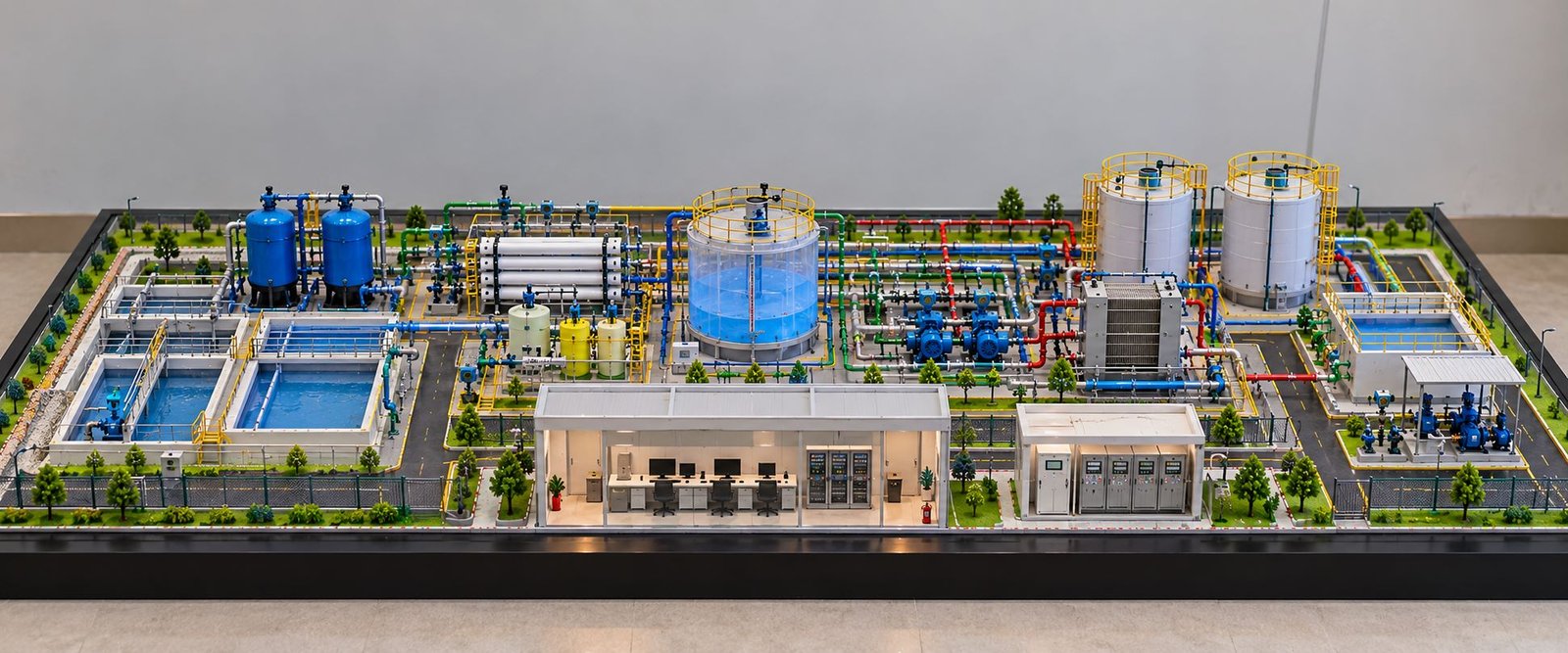
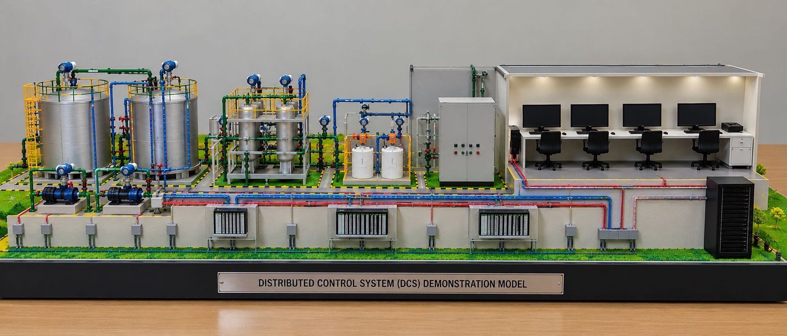
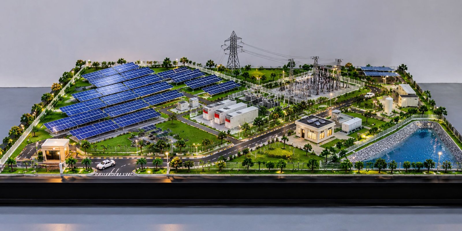
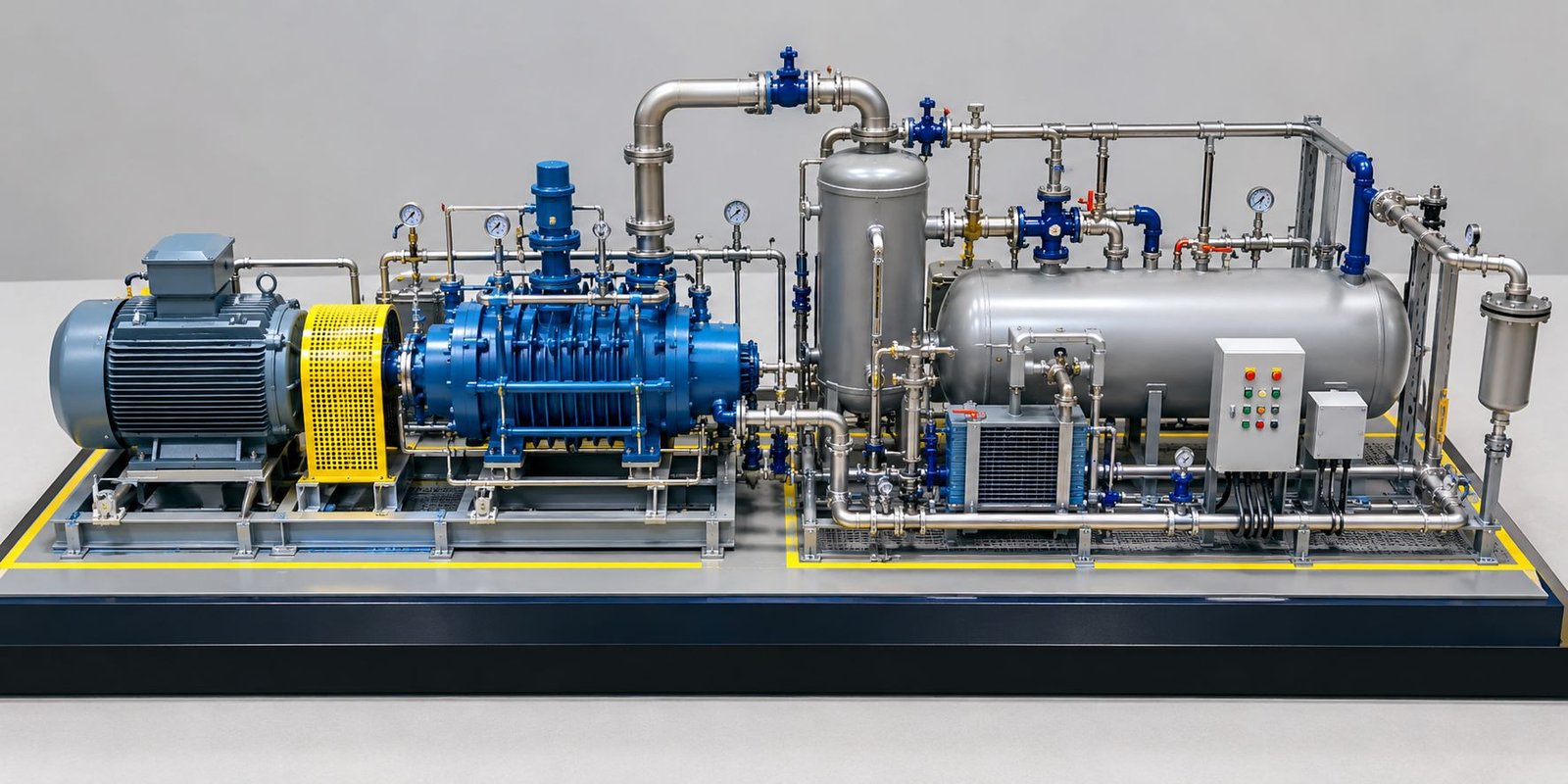
Companies may also require power plant scale models, industrial equipment models, pump and motor models, piping engineering models, oil refinery models, factory layout models, electrical substation models, process plant models, and infrastructure engineering models.
Some projects combine industrial equipment with architectural structures, control rooms, service areas, and surrounding site layouts.
CAD drafting, 3D modeling, laser cutting, CNC fabrication, and 3D printing can support these projects. However, the model maker should select the production method according to the required dimensions, material, and component complexity.
For a custom engineering model, clients should share the intended application, available drawings, preferred scale, overall dimensions, required details, and presentation requirements.
This information helps the design team prepare a suitable model plan before fabrication begins.
How to Choose a DG Set Model Making Company
Choosing the right model maker can improve both technical accuracy and presentation quality.
First, review the company’s portfolio to check its experience with industrial equipment, machinery, engineering models, and complex assemblies.
Next, discuss the available technical references. A professional team should understand how to use photographs, CAD files, dimensional drawings, and equipment layouts during design development.
Also, confirm the model scale, display base dimensions, fabrication materials, paint finish, enclosure requirements, and delivery schedule.
If the project requires an open-type generator, explain which components must remain visible. For example, you may want a clearly defined exhaust silencer, a visible chimney, detailed radiator connections, and a realistic control panel.
Similarly, if the project requires a soundproof generator, share the enclosure design and identify any internal details that need special treatment.
Finally, review the proposed design before fabrication. This step allows the team to correct proportions and component positions early in the process.
PAL Design Models provides architectural, industrial, and engineering model-making services. To discuss a custom engineering model or industrial presentation project, visit https://paldesignmodels.com.
Frequently Asked Questions About DG Set Engineering Models
What is a DG set engineering model?
A DG set engineering model is a scaled physical representation of a diesel generator. It can show the engine, alternator, radiator, exhaust system, control panel, batteries, and supporting frame.
Which parts should a diesel generator scale model include?
The model can include the diesel engine, alternator, radiator, fan, exhaust pipe, silencer, chimney or exhaust stack, intake system, filters, batteries, control panel, wiring, mounting brackets, and base skid. The final selection depends on the actual generator design.
Can a model maker use 3D printing for a DG set model?
Yes. 3D printing can produce complex engine housings, brackets, filters, and other custom components. The model maker can combine printed parts with laser-cut panels, metal tubes, and hand-fabricated details.
What is the difference between an open-type and a soundproof DG set model?
An open-type model exposes most of the generator components. A soundproof model represents the equipment with an acoustic enclosure, ventilation grilles, access doors, and other external features.
Why does scale accuracy matter in engineering model making?
Correct scale helps maintain realistic proportions between the engine, alternator, radiator, and other components. It also makes the model more useful for technical presentations and equipment visualization.
Can the model include a separate exhaust silencer and chimney?
Yes. The model maker can show the exhaust pipe, silencer body, connecting joints, support brackets, and visible outlet stack according to the reference design.
Which industries use DG set scale models?
Generator manufacturers, EPC contractors, industrial facilities, engineering consultants, equipment suppliers, educational institutes, and exhibition organizers can use DG set models for presentations, training, and product demonstrations.
Final Thoughts
A detailed DG Set Engineering Model brings the main components of a diesel generator into one clear and realistic physical assembly. The engine, alternator, radiator, exhaust pipework, silencer, chimney, fuel connections, batteries, control panel, and base frame should all follow the actual equipment layout.
Correct proportions matter just as much as fine detailing. Therefore, the model maker should study the reference drawings, select a suitable scale, and plan every major component before fabrication begins.
In addition, careful material selection, accurate assembly, realistic painting, and clean finishing help create a professional industrial model.
Whether a project requires an open-type DG set, a soundproof generator, or a custom industrial equipment model, a reference-based approach can produce a more technically accurate result.
For industrial exhibitions, engineering presentations, technical education, and project visualization, a well-made diesel generator scale model offers a practical way to explain complex equipment and demonstrate the value of precision engineering model making.