Electrical Substation Models: Detailed Scale Models for Power Infrastructure Projects
Electrical substations play an essential role in modern power transmission and distribution networks. These facilities manage, transform, protect, and distribute electrical power between different sections of an electricity system. Since a substation contains transformers, switchgear, busbars, gantries, insulators, control equipment, cables, transmission structures, and safety infrastructure, explaining the complete arrangement through conventional drawings can sometimes become difficult. Electrical Substation Models provide an effective way to represent these complex installations in a clear three-dimensional format.
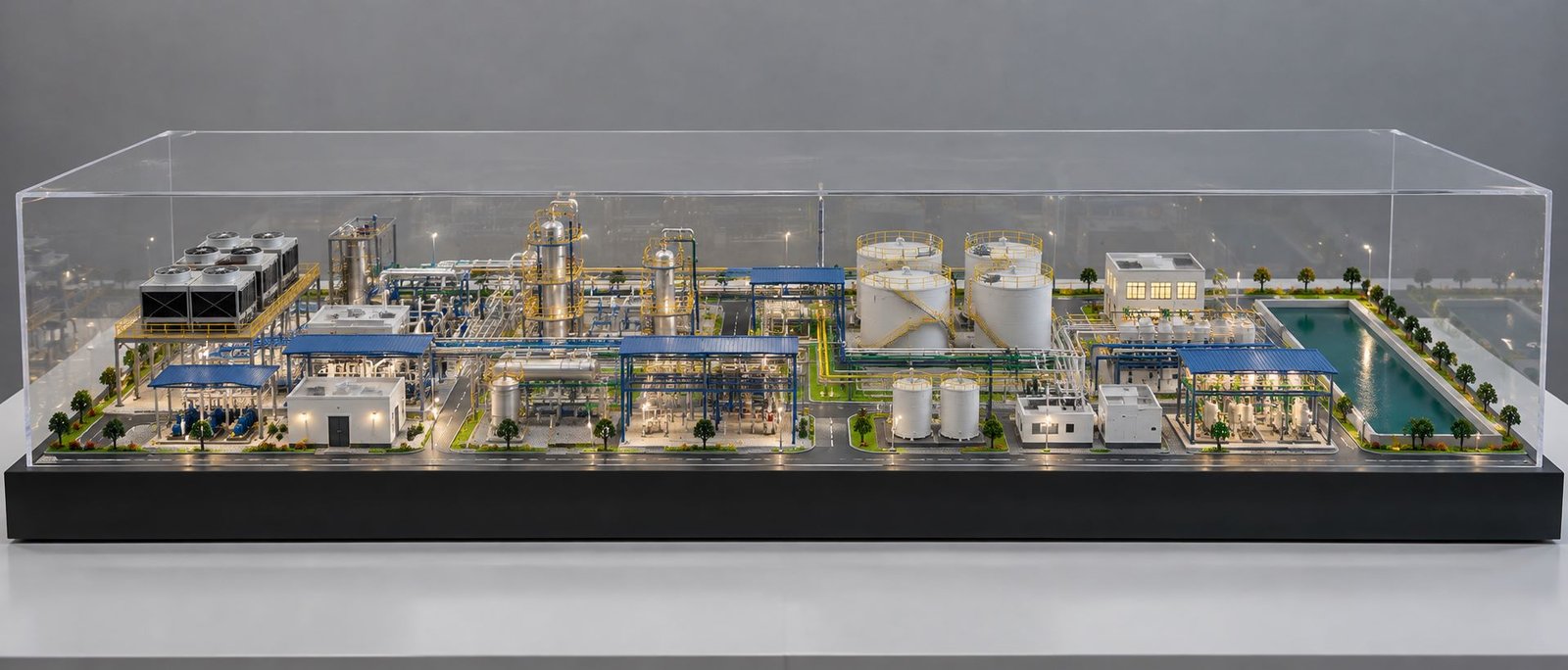
A professional scale model can show the complete substation layout, equipment positioning, internal roads, fencing, control buildings, transformer areas, switchgear sections, transmission structures, and other important components on one platform. Moreover, stakeholders can view the project from different angles and understand the physical relationship between individual systems. This makes a model particularly useful for engineering presentations, project discussions, exhibitions, investor meetings, training, and infrastructure demonstrations.
Modern model-making techniques also allow complex electrical equipment to receive highly detailed treatment. For example, 3D printing can reproduce transformers, breakers, insulators, control cabinets, and other custom components. Laser cutting, acrylic fabrication, metal detailing, precision handcrafting, miniature wiring, and LED lighting can further improve the overall appearance and presentation.
What Are Electrical Substation Models?
Electrical Substation Models are physical scale representations of electrical substations created according to engineering drawings, CAD files, BIM data, 3D models, or approved project layouts. Such models reproduce the major components and spatial arrangement of a substation at a selected scale. Depending on the project requirements, the model can represent a transmission substation, distribution substation, switching station, renewable-energy substation, or industrial electrical facility.
Different components can appear within the same presentation. Transformers, circuit breakers, isolators, current transformers, potential transformers, busbars, lightning arresters, cable trenches, control panels, gantry structures, insulators, fencing, gates, roads, control rooms, and transmission connections can all form part of the model. As a result, stakeholders can understand the complete site arrangement from a single physical presentation.
Model detailing can also vary according to the intended application. A presentation model may focus on equipment positioning and overall site planning. In contrast, a detailed engineering model can reproduce individual insulators, connectors, busbars, support brackets, cables, control cabinets, transformer cooling systems, safety barriers, and access roads.
Importance of Electrical Substation Scale Models
Large substations contain numerous components within a relatively limited area. Consequently, understanding their physical relationship through only two-dimensional drawings can become challenging. A three-dimensional model converts the technical layout into a physical form that viewers can examine from different directions.
Engineers can use the model to study transformer positions, switchgear bays, busbar arrangements, control buildings, access routes, and equipment clearances. Meanwhile, project managers can use the same model to explain the proposed facility to clients and non-technical stakeholders.
Another important advantage comes from improved communication. Team members can directly point toward equipment, buildings, roads, or specific sections during a discussion. Therefore, everyone can use the physical model as a common visual reference.
For large infrastructure projects, a Power Infrastructure Model can also communicate the relationship between the electrical facility and the surrounding development. Furthermore, the model can become a valuable presentation asset when a project needs to be explained to people who may not regularly work with engineering drawings.
Types of Electrical Substation Models
Different electrical projects require different types of substation models. The appropriate model usually depends on voltage level, site size, equipment arrangement, project stage, and intended application.
Transmission Substation Models
Transmission substations handle high-voltage power transmission and often cover large areas. A detailed Transmission Substation Model can include transformer banks, large gantry structures, transmission lines, busbar arrangements, circuit breakers, isolators, instrument transformers, and protection equipment.
Large transmission facilities require careful scale planning because many structures must fit within one presentation area. Additionally, the model can show transmission towers and overhead conductors entering or leaving the substation. This helps viewers understand how the facility connects with the wider transmission network.
A high-voltage installation may contain numerous equipment bays arranged in a specific sequence. Therefore, accurate equipment placement becomes particularly important when creating a High Voltage Substation Model.
Distribution Substation Models
Distribution substations operate closer to consumers and distribute electrical power through local networks. Their models can include transformers, switchgear, distribution panels, cable routes, control equipment, fencing, compact buildings, and incoming or outgoing feeders.
Such a model can demonstrate how electrical energy moves from higher-voltage systems into local distribution networks. Furthermore, it can support technical presentations, training programs, educational demonstrations, and infrastructure discussions.
The compact nature of many distribution facilities also allows model makers to show a greater level of equipment detail. As a result, smaller-scale electrical infrastructure can still receive a highly detailed physical representation.
Industrial Substation Models
Large manufacturing plants, refineries, chemical facilities, steel plants, warehouses, and other industrial projects often require dedicated electrical substations. An Industrial Substation Model can show the relationship between the electrical facility and the surrounding industrial development.
For example, the model may contain transformers, electrical rooms, switchgear, cable corridors, utility buildings, industrial roads, pipe racks, process areas, and maintenance access. Consequently, the substation can become part of a larger industrial plant model.
This approach is particularly useful when electrical infrastructure is an important part of a larger EPC or industrial project.
Renewable Energy Substation Models
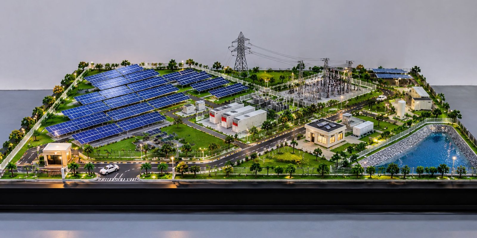
Solar parks and wind farms require electrical infrastructure to collect and transmit generated power. A renewable-energy substation model can represent transformers, switchgear, control rooms, collection systems, transmission structures, and grid connections.
Moreover, a complete solar or wind project model can show the generation area together with its substation. This gives investors and stakeholders a better understanding of the complete energy infrastructure.
Solar panels, wind turbines, transmission lines, control buildings, roads, and landscaping can be integrated into the same presentation. Therefore, renewable-energy projects can use physical models to communicate both generation and electrical distribution systems.
Major Components of an Electrical Substation Model
A professional substation model combines electrical equipment, structural elements, civil infrastructure, safety systems, and landscape features. Each component contributes to the overall understanding of the facility.
Power Transformers
Power transformers often become the most prominent equipment within a substation. A detailed miniature version can include the transformer tank, radiators, bushings, conservator tank, cooling fans, support structure, and cable connections.
Accurate positioning also helps demonstrate the relationship between transformer bays and nearby equipment. Furthermore, detailed transformer construction can significantly improve the technical appearance of the complete model.
A Transformer Scale Model can be manufactured using a combination of fabricated parts, 3D-printed components, acrylic, metal elements, and miniature detailing. As a result, even a large transformer installation can be represented realistically at a selected scale.
Circuit Breakers
Circuit breakers form an important part of substation protection and switching systems. Their miniature representation can include the main body, operating mechanism, terminals, support insulators, and connection points.
As a result, properly detailed breakers help viewers identify individual electrical bays. Their placement should follow the approved engineering layout so that the model maintains technical accuracy.
Isolators and Disconnectors
Isolators or disconnectors form another important part of an outdoor switchyard. These components normally connect different sections of electrical equipment while maintaining the required separation.
A miniature version can reproduce isolator blades, operating mechanisms, support insulators, and mounting structures. Therefore, these details contribute to the realistic appearance of the switchyard.
Busbars and Conductors
Busbars connect different electrical bays and equipment within the substation. Their configuration provides important information about the electrical arrangement.
Thin metal rods, wires, or specially fabricated components can represent miniature busbars and conductors. Moreover, their positioning can clearly demonstrate connections between transformers, breakers, isolators, and other equipment.
Insulators
Insulators support electrical conductors while maintaining electrical isolation from grounded structures. Their small size makes them challenging to manufacture manually, especially when a project requires many repeated components.
3D printing, resin casting, acrylic fabrication, and miniature ceramic-like materials can provide suitable solutions. Consequently, detailed insulators can improve both realism and technical presentation quality.
Substation Gantry Structures
Gantry structures support busbars, incoming lines, outgoing lines, and other electrical connections. Their framework creates one of the most recognizable visual features of an outdoor switchyard.
Metal profiles, thin aluminium sections, laser-cut components, and other miniature structural materials can reproduce these structures. Additionally, cross members, vertical supports, insulator mounting points, and conductor connections can receive detailed treatment.
Proper proportions remain important throughout the structure. For this reason, the model maker should maintain the same scale across gantries, electrical equipment, buildings, roads, and other components.
Large gantries can become dominant visual elements in a substation presentation. Therefore, their dimensions should be balanced carefully with transformers and other equipment so that the final model remains realistic.
Control Room and Auxiliary Buildings
Control rooms provide space for protection systems, monitoring equipment, communication systems, batteries, and other supporting electrical infrastructure. A scale model can reproduce these buildings with doors, windows, ventilation systems, roof structures, and access pathways.
Furthermore, the surrounding area can include parking spaces, landscaping, lighting, security fencing, and maintenance access. Such details help viewers distinguish operational buildings from outdoor switchyard equipment.
Control buildings can also include miniature electrical panels and equipment layouts when the project requires a higher level of detail. As a result, the building becomes an important part of the overall engineering presentation.
Roads and Internal Access
Internal roads provide access for maintenance vehicles and heavy equipment. Transformer transportation, equipment replacement, inspection activities, and emergency access all require suitable circulation areas.
A detailed model can represent internal roads, turning spaces, equipment access points, parking areas, and pedestrian pathways. Moreover, road markings and miniature streetlights can make the site layout easier to understand.
Heavy equipment areas may require wider access routes than ordinary maintenance areas. Therefore, the road arrangement should follow the approved project layout.
Miniature vehicles can also be added where required. In addition, landscaped road edges and safety markings can make the site appear more realistic without distracting from the electrical equipment.
Substation Fencing and Security
Security fencing generally surrounds outdoor electrical substations. A professional model can reproduce perimeter fencing, gates, security barriers, access points, and boundary structures.
Fine mesh, metal wire, acrylic, or laser-cut materials can create realistic miniature fencing. Similarly, entrance areas can include security cabins, barriers, lighting, and controlled access points.
These features complete the site presentation and help define the operational boundary of the substation. Moreover, security elements can demonstrate how the electrical installation is physically separated from surrounding areas.
Lighting for Electrical Substation Models
Lighting can significantly improve the visual impact of an electrical substation model. Small LEDs can represent streetlights, equipment-area lighting, control-room illumination, security lights, and perimeter lighting.
Moreover, carefully positioned lighting can highlight transformers, switchgear, control buildings, and major structures during presentations. A day-and-night model can also demonstrate how the facility may appear after dark.
Warm or neutral lighting can create an attractive presentation without hiding engineering details. Therefore, the lighting system should complement the model instead of becoming its main visual feature.
Programmable lighting can also be used for advanced presentations. For example, separate sections can be illuminated to highlight a transformer bay, switchgear area, transmission connection, or control building.
Materials Used for Substation Model Making
Several materials can help reproduce electrical equipment and supporting infrastructure. Common choices include acrylic, MDF, PVC, ABS plastic, metal wire, aluminium sections, resin, foam board, transparent sheets, and 3D-printed materials.
Acrylic
Acrylic works well for transparent panels, windows, protective barriers, and selected electrical components. Additionally, thin acrylic sheets can create clean and precise miniature structures.
MDF
MDF provides a strong foundation for large model bases and structural sections. Roads, buildings, equipment platforms, and landscape areas can also use MDF as a supporting material.
Metal and Wire
Thin metal rods and wires can reproduce gantries, conductors, busbars, support structures, and transmission connections. As a result, these materials can provide realistic structural detailing.
3D Printing
3D printing offers considerable flexibility for complicated electrical components. Transformers, breakers, insulators, control cabinets, support structures, electrical panels, and custom equipment can be manufactured from digital designs.
Furthermore, repeated components can receive consistent dimensions through digital manufacturing. This advantage becomes particularly valuable when a large substation contains many identical equipment units.
Laser Cutting
Laser cutting can produce precise building parts, equipment housings, fencing, structural components, road elements, and miniature architectural details.
Therefore, combining laser cutting with 3D printing can produce a detailed and consistent engineering model.
Traditional handcrafting also remains useful for very small components and customized details. Meanwhile, fine wires, rods, sheets, and miniature hardware can be shaped and assembled according to the project requirements.
Choosing the Right Scale
Scale selection plays an important role in electrical substation model making. Large facilities contain numerous components, so the model must balance overall site dimensions with the visibility of individual equipment.
A smaller scale can represent a large site within a manageable baseboard. In contrast, a larger scale provides greater visibility for detailed equipment and structural elements.
Several factors influence scale selection, including site area, equipment dimensions, available display space, transportation requirements, presentation purpose, and budget. For example, an exhibition model may require a practical size that visitors can view comfortably from multiple sides.
An engineering demonstration model may follow a different approach. Meanwhile, a detailed training model can prioritize equipment visibility over portability.
3D Printing for Electrical Substation Scale Models
Digital manufacturing has expanded the possibilities of engineering model making. 3D printing allows manufacturers to create accurate miniature versions of complicated electrical components.
Transformers, breakers, insulators, control cabinets, support structures, panels, and custom equipment can be developed from digital 3D designs. Moreover, modifications can be made digitally when project requirements change.
Repeatability provides another important benefit. Identical components can be manufactured with consistent dimensions, which improves the overall appearance of a large substation model.
However, not every part needs to be 3D printed. Acrylic, PVC, metal wire, aluminium, laser-cut components, and handcrafted parts can be combined with printed components. As a result, the final Electrical Substation Scale Model can achieve a balanced combination of precision, durability, and visual realism.
Interactive Electrical Substation Models
Advanced models can include interactive features such as LED lighting, switches, touchscreens, digital displays, and programmable controls.
Different lighting zones can highlight transformer bays, incoming lines, outgoing feeders, control rooms, or switchgear sections. As a result, presenters can explain individual areas without confusing the audience.
Interactive models are especially useful for exhibitions, training facilities, technical demonstrations, investor presentations, and educational environments. Furthermore, interactive functions can make complex electrical infrastructure easier to understand for visitors who do not have an engineering background.
Cutaway and Sectional Substation Models
A conventional model usually presents the exterior arrangement of equipment. However, certain projects require viewers to understand internal systems as well.
Cutaway and sectional models can expose cable routes, internal equipment, electrical panels, transformer components, or control systems. Therefore, these models can provide a deeper technical understanding than a standard exterior presentation.
Training centres can particularly benefit from sectional models because trainees can observe components that normally remain enclosed. Additionally, a sectional model can focus attention on one specific equipment system without requiring a complete substation installation.
Electrical Substation Models for EPC Companies
EPC companies manage complex engineering and infrastructure projects that often involve multiple technical disciplines. During project presentations, teams may need to explain the physical arrangement of electrical systems to clients and stakeholders.
A detailed substation model provides a common visual reference for these discussions. Moreover, EPC teams can use it during design reviews, client meetings, tender presentations, progress discussions, and exhibitions.
Electrical engineers, civil engineers, structural teams, construction professionals, and project managers can all refer to the same physical representation. Consequently, communication becomes easier across different project disciplines.
An EPC Project Model can also integrate the electrical substation with other project facilities. For example, an industrial development model may show the substation alongside process buildings, storage areas, roads, utility systems, and other infrastructure.
Electrical Substation Models for Utility Companies
Power utilities can use scale models to present planned infrastructure projects. New substations, expansion projects, transmission connections, equipment upgrades, and distribution infrastructure can all appear within one physical presentation.
Additionally, a model can help explain complex infrastructure to government representatives, investors, visitors, and other stakeholders.
Permanent displays can also become useful inside utility offices, technical centres, project information facilities, and exhibition areas. As a result, the model can continue to communicate the project long after its original presentation.
Electrical Substation Models for Training
Training centres can use physical substation models to explain electrical equipment and site layouts. Trainees can identify transformers, breakers, isolators, busbars, control buildings, cable routes, and safety zones through a three-dimensional reference.
Furthermore, interactive lighting can highlight selected equipment during training sessions. This method can make technical explanations easier to follow.
A physical model cannot replace technical training or approved safety procedures. Nevertheless, it can serve as a valuable visual supplement for understanding the physical arrangement of a substation.
Students and new technical professionals can also use such models to develop a better understanding of equipment relationships. Similarly, experienced teams can use sectional or detailed models for specialized demonstrations.
Presentation and Exhibition Applications
Electrical substation models can create a strong visual impact at engineering exhibitions and infrastructure events. A large, detailed model can attract attention while communicating the complexity of a power project.
For instance, an EPC company can display a substation model at an industry exhibition to demonstrate its engineering capabilities. A utility company can similarly use a model to explain a proposed power infrastructure project.
Lighting, transparent covers, detailed equipment, landscaping, and a clean baseboard can further improve the exhibition presentation. Moreover, a well-finished model can become a permanent display for corporate offices and project experience centres.
Accuracy and Engineering Detailing
Accuracy remains a key requirement when developing an electrical substation model. Equipment locations, bay arrangements, transformer positions, gantry heights, road layouts, control buildings, and major connections should follow approved engineering information.
At the same time, visual clarity also matters. Therefore, model makers need to balance technical accuracy with presentation requirements.
Some small components can use simplified detailing when exact reproduction does not improve communication. However, major equipment and important structures should maintain correct proportions and positions.
This approach keeps the model informative without making the presentation unnecessarily crowded. Furthermore, consistent detailing across repeated equipment can improve the professional appearance of the complete model.
Customization of Electrical Substation Models
Every electrical project has different requirements. Therefore, manufacturers can customize substation models according to project drawings, engineering data, and presentation objectives.
Customization may include transformer designs, switchgear arrangements, gantry structures, busbar configurations, transmission towers, control buildings, internal roads, fencing, lighting, landscaping, cable routes, equipment platforms, safety areas, and drainage systems.
Large models can also use modular construction. Separate sections can be manufactured individually and assembled at the final location. Furthermore, modular construction can simplify transportation, installation, and maintenance.
A customized Power Substation Model can also include company-specific presentation requirements, selected equipment details, removable sections, lighting controls, protective enclosures, and project-specific landscaping.
Baseboard and Protective Enclosure
The baseboard provides structural support for the complete substation model. A strong foundation helps maintain equipment alignment and protects delicate miniature components.
For exhibition applications, a transparent acrylic or glass enclosure can provide additional protection. Moreover, the enclosure can reduce dust accumulation on small electrical components and landscaping.
A black, white, or neutral baseboard can create a professional presentation appearance. Meanwhile, the overall base dimensions should maintain a suitable border around the complete site.
Large models may require sectional or modular bases. As a result, individual sections can be transported more safely and assembled at the exhibition or project location.
Benefits of Professional Substation Model Making
Professional Substation Model Making provides several benefits for complex electrical projects. First, the model offers a three-dimensional understanding of equipment placement. Second, it provides a common visual reference for technical and non-technical stakeholders.
Moreover, a physical model can improve project presentations because viewers can examine the facility from multiple angles. Equipment relationships, access routes, buildings, and infrastructure become easier to identify.
Another advantage is customization. The model can be designed specifically around the project’s engineering drawings, selected scale, presentation requirements, lighting needs, and available display space.
Consequently, a professionally developed model can serve multiple purposes throughout the project lifecycle, from engineering discussions and design reviews to exhibitions, training, and final presentations.
Future of Electrical Substation Model Making
The future of electrical substation model making will increasingly combine physical craftsmanship with digital engineering technologies. BIM, CAD, 3D printing, laser cutting, digital fabrication, LED systems, and interactive displays can improve both accuracy and presentation quality.
Digital engineering data can provide detailed information for model production. Meanwhile, advanced manufacturing can convert selected digital components into precise physical parts.
Augmented reality and digital displays may also complement physical models in future applications. However, physical models will continue to provide an important advantage because viewers can understand the actual spatial relationship between equipment and infrastructure.
As electrical infrastructure becomes more complex, the need for clear project visualization will continue to grow. Therefore, detailed engineering models are likely to remain valuable tools for communication, education, presentation, and project development.
Conclusion
Electrical Substation Models provide an effective way to visualize complex power infrastructure projects in a clear three-dimensional format. Transformers, circuit breakers, isolators, busbars, insulators, gantries, transmission structures, control buildings, roads, fencing, lighting, and landscaping can come together within one professionally designed model.
Moreover, modern techniques such as 3D printing, laser cutting, acrylic fabrication, metal detailing, precision handcrafting, miniature wiring, and LED lighting allow manufacturers to achieve high levels of precision and realism. These methods also make it easier to reproduce complex electrical equipment and repeated components.
EPC companies, electrical consultants, utility companies, engineering firms, infrastructure developers, power-generation companies, and project management teams can use these Electrical Engineering Models for project presentations, design reviews, exhibitions, technical demonstrations, training, investor meetings, and client discussions.
Ultimately, a professional electrical substation model does more than create a miniature version of a power facility. It transforms complex engineering information into a clear physical presentation that helps people understand equipment placement, site planning, connectivity, safety zones, access routes, and the overall infrastructure concept.