How Piping Models Help Engineers Better Understand Plant Layouts
Piping plays an important role in understanding the layout of modern industrial plants. These facilities contain many interconnected systems, including pipes, valves, pumps, tanks, vessels, pipe racks, platforms, walkways, and utility systems. Engineers need to understand how these components connect and occupy the available space. However, studying separate drawings, CAD models, P&IDs, and digital 3D models can sometimes make the complete physical arrangement difficult to visualize.
A piping model provides a clear three-dimensional view of the plant. It helps engineers see how pipelines connect different equipment, how pipe racks are arranged, and how various systems use the available space. In addition, it can support design discussions, engineering reviews, project presentations, training, and plant planning.
The main benefit comes from seeing the complete plant in one physical view. Engineers can look at equipment, pipelines, structures, platforms, roads, and access areas together. As a result, they can understand the relationship between different parts of the plant more easily.
Understanding the Overall Plant Arrangement
A large industrial plant can have many different sections. Engineers may receive separate drawings for process equipment, piping, structures, utilities, electrical systems, roads, and buildings.
Each drawing provides useful information. However, engineers may need to study several drawings to understand how all the components fit together.
A detailed piping scale model brings these components into one physical layout.
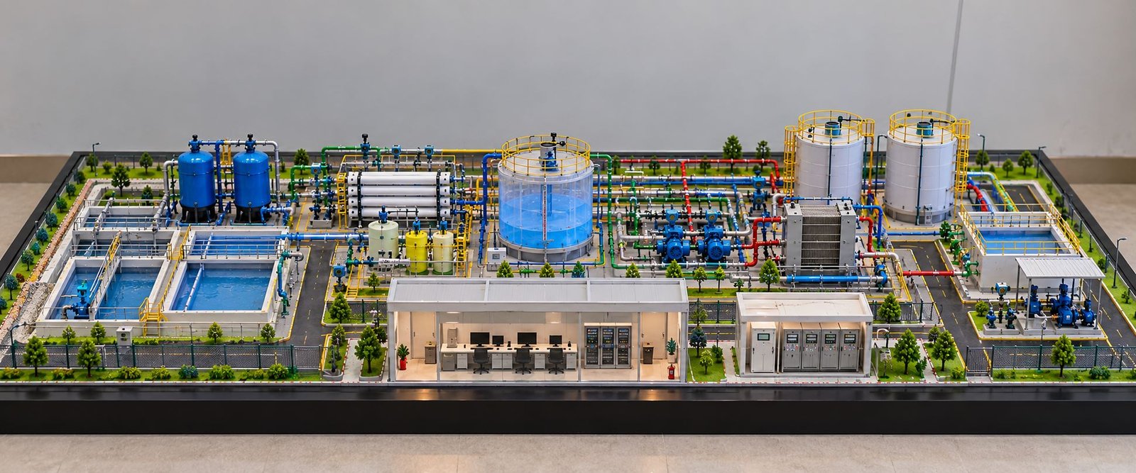
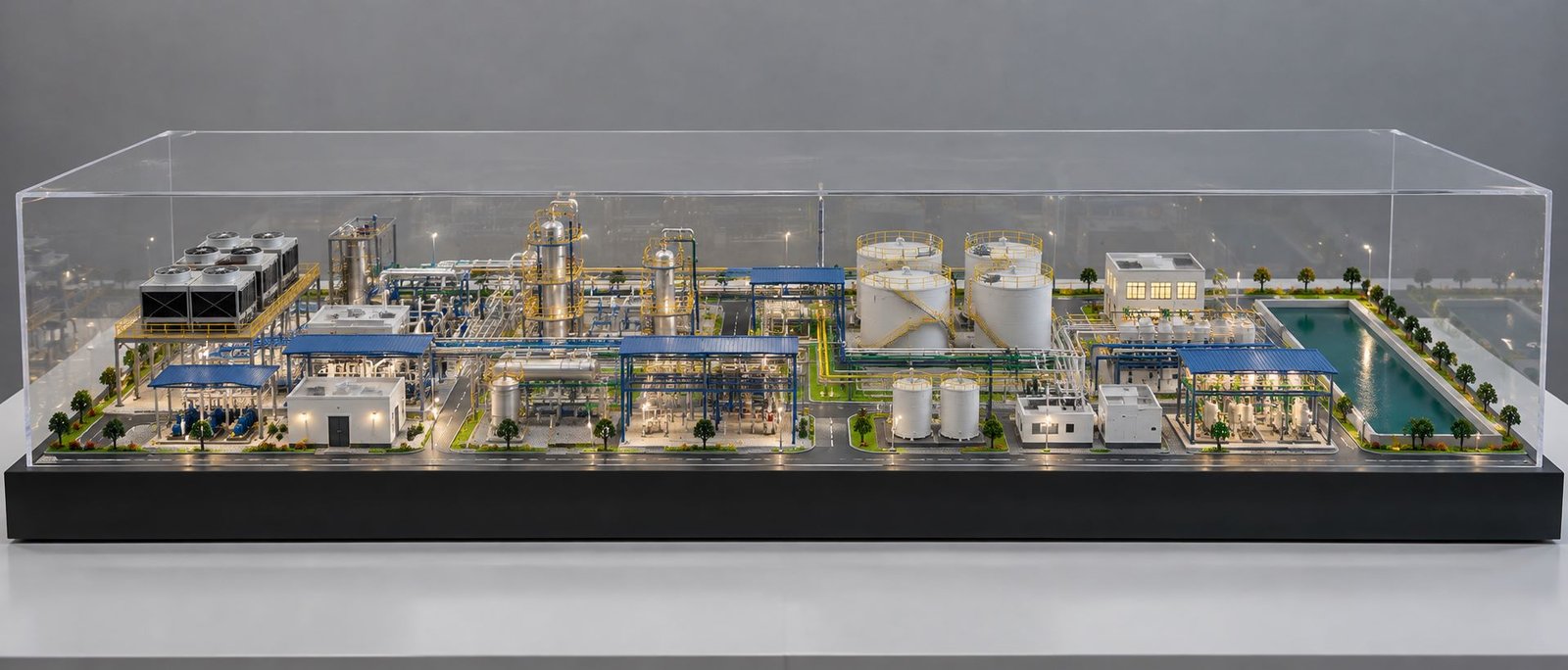
The model can show storage tanks, pressure vessels, pumps, compressors, process columns, heat exchangers, pipe racks, pipelines, platforms, roads, and other important elements. In this way, engineers can view the complete arrangement from one physical model.
For example, a process vessel may stand near a pump while several pipelines connect both areas through a pipe rack. A drawing may show these components from different views. On the other hand, the physical model shows their positions together.
This visual connection helps engineers understand the plant layout more clearly.
Seeing Equipment and Piping Together
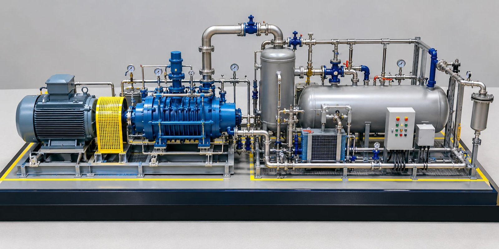
Equipment and pipelines work as connected systems. A pump needs suction and discharge lines. A vessel may have several inlet and outlet pipelines. Similarly, a heat exchanger may connect with multiple process lines.
A physical model shows these connections together. As a result, engineers can follow a pipeline from one piece of equipment to another and understand how the system moves through the plant.
Visualizing Pipe Routing in Three Dimensions
Pipe routing plays an important role in plant layout design.
Industrial pipes rarely follow only one straight path. A pipeline may change direction, rise to another level, pass through a pipe rack, connect to equipment, or move around a structure.
A piping model shows these changes in three dimensions.
Engineers can see horizontal pipes, vertical pipes, elbows, branches, supports, connections, and changes in height. Moreover, they can view the model from the front, side, or top.
Each viewing angle provides a different understanding of the same piping system.
This becomes especially useful when several pipelines share the same area. For example, engineers can see which pipe runs above another pipe, where a pipeline changes direction, and how a line reaches an equipment nozzle.
In addition, they can follow several process lines through a pipe rack. Therefore, the three-dimensional model makes complex routing easier to understand.
Understanding Complex Pipe Connections
Complex connections can become difficult to explain through words alone.
A physical model allows an engineer to point directly at the connection and explain the routing. Other team members can see the same location at the same time.
Because of this, the model creates a simple visual method for discussing complex piping arrangements.
Understanding Pipe Rack Arrangements
Pipe racks often contain a large number of pipelines in a small area. They may also carry cable trays, utility lines, structural members, and other services.
Therefore, pipe racks form an important part of plant layout planning.
A pipe rack model shows the complete arrangement in three dimensions.
Engineers can examine different rack levels, pipeline spacing, pipe direction, support positions, and connections with process areas. At the same time, the model shows how pipelines use different vertical levels.
For example, one pipeline may run at a lower level while another line passes above it. A physical model makes this difference easy to see.
Why Pipe Rack Visualization Helps Engineers
Engineers can use the model during design meetings to discuss specific areas of a pipe rack.
Instead of opening several sectional drawings, the team can look at the physical model and point to the required area. As a result, everyone can use one common visual reference during the discussion.
This approach can make pipe rack coordination easier.
Seeing the Relationship Between Equipment and Piping
Pipelines connect different types of industrial equipment.
These may include:
- Pumps
- Tanks
- Reactors
- Compressors
- Heat exchangers
- Pressure vessels
- Process columns
- Storage vessels
Each equipment item may require several pipelines.
For example, a pump may have suction and discharge lines. The suction line may come from a tank, while the discharge line may travel toward another process unit.
A piping model shows these connections in their physical positions.
Therefore, engineers can see how equipment and pipelines occupy the available area together.
The model can also show how equipment orientation affects piping. If an engineer changes the position or direction of a piece of equipment, nearby pipelines may also need changes.
Because of this, the physical model makes the relationship easier to discuss.
Why Equipment Orientation Matters
Equipment orientation can affect pipeline direction, connection points, access routes, and maintenance space.
In addition, the position of equipment can influence nearby pipe routing.
When engineers see equipment and piping together, they can discuss these relationships more clearly.
Identifying Spatial Relationships in Plant Layout
Industrial plants have limited space.
Engineers need to arrange equipment, pipes, structures, roads, walkways, platforms, and maintenance areas within the available site.
A piping model helps engineers understand how these components use the available space.
The model can show areas with high equipment density and areas with more open space. Furthermore, engineers can observe the distance between equipment and pipelines.
This helps them understand the proportions of the plant.
A pipe may look very small on a large CAD drawing. However, when engineers see the same pipe next to equipment and structures in a physical model, they can understand its physical position more easily.
Making Elevation Changes Easier to Understand
Industrial plants use both horizontal and vertical space.
Some pipelines run close to ground level. Other pipelines rise through pipe racks or move around tall process equipment.
Two-dimensional drawings can show these levels. However, engineers may need to study several views to understand the complete arrangement.
A scale model provides a direct three-dimensional view.
The model can include vertical pipes, elevated pipe racks, platforms, towers, ladders, walkways, and equipment.
As a result, engineers can see how different systems use the vertical space of the plant.
This becomes especially useful in areas where many pipelines run at different levels.
Understanding Vertical Plant Space
A plant layout does not only use the floor area. It also uses the space above the ground.
Pipe racks, platforms, vessels, towers, and elevated pipelines all occupy vertical space.
In this way, a piping model helps engineers see the complete arrangement at the same time.
Supporting Engineering Design Review Meetings
Engineers from different disciplines often take part in plant design reviews.
A process engineer may focus on equipment and process connections. A piping engineer may focus on pipe routing. A structural engineer may examine supports and platforms. Meanwhile, other project teams may focus on access, maintenance, or overall plant arrangement.
A physical piping model gives all these teams one common reference.
Engineers can point to a specific part of the model and discuss the design around that area.
As a result, technical discussions can become easier because everyone can look at the same physical arrangement.
The model does not replace detailed engineering drawings or calculations. Instead, it adds another visual method for understanding the plant.
Helping Engineers Understand Congested Plant Areas
Some areas of an industrial plant contain many components within a small space.
These areas may include:
- Multiple pipelines
- Valves
- Equipment connections
- Pipe supports
- Platforms
- Structures
- Walkways
- Access routes
Engineers may find such areas difficult to understand through drawings alone.
A detailed piping model makes the arrangement easier to see.
Engineers can view the congested area from different directions. In addition, they can follow individual pipes and see how different systems share the same space.
The model can also help the team identify areas that need further design review.
However, engineers should continue to use approved drawings and calculations for detailed engineering decisions. The physical model provides additional visual understanding.
Understanding Access and Maintenance Areas
Industrial equipment needs regular inspection and maintenance.
Engineers therefore need to consider access around pumps, compressors, vessels, heat exchangers, valves, and other equipment.
A piping model can show platforms, ladders, walkways, maintenance areas, and operating spaces.
For example, a valve on an elevated pipeline needs suitable access. Engineers can look at the model and see the valve position in relation to the platform or walkway.
Similarly, the model can help teams discuss maintenance space around pumps, compressors, and other equipment.
Visualizing Maintenance Access
Maintenance teams need enough space to inspect, remove, repair, or replace equipment.
A physical model helps engineers discuss these areas during design reviews.
As a result, the team gets a clear visual reference for access and maintenance planning.
Improving Communication Between Technical Teams
Large industrial projects involve many teams.
Engineers, project managers, contractors, clients, designers, and consultants may all work on the same project.
Not everyone works with technical drawings every day.
A physical model can make communication easier.
An engineer can point directly to a pipe, equipment item, pipe rack, platform, or process area while explaining a design issue.
At the same time, other team members can look at the same physical component.
This approach can help when teams discuss complex plant layouts with clients, project managers, contractors, trainees, or other stakeholders.
Using Color Coding to Understand Different Piping Systems
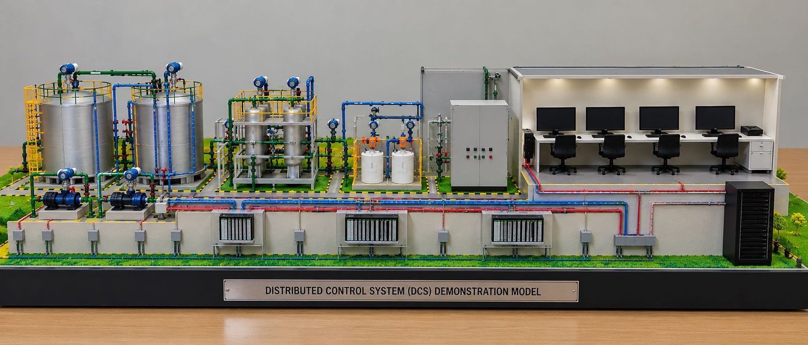
Color coding can make a piping model easier to read.
Different colors can represent different piping systems according to the project’s requirements.
For example, a model may use separate colors for:
- Process pipelines
- Water pipelines
- Steam systems
- Fuel lines
- Cooling systems
- Utility lines
Color coding does more than improve the appearance of a model.
It helps engineers follow different systems through the plant. Therefore, when many pipelines run close to one another, color differences can make each system easier to identify.
Representing Valves, Flanges and Pipe Fittings
Small piping components can provide important information.
A detailed piping model may include valves, flanges, elbows, reducers, branches, supports, nozzles, and other fittings.
These details help engineers understand how a pipeline connects and changes direction.
For example, valves can show control or isolation points. Flanges can indicate connection locations. Elbows show changes in direction. Similarly, reducers show changes in pipe size, while branches show connections to other lines.
As a result, accurate small details can make the model more useful for engineering visualization.
Why Small Piping Details Matter
Small components may look minor, but they can help engineers understand the construction and arrangement of a piping system.
However, the model does not always need every small component. The project purpose determines the required level of detail.
Supporting Multidisciplinary Plant Layout Coordination
Plant layout involves many engineering disciplines.
Piping, mechanical, structural, electrical, instrumentation, and civil systems all need space within the same plant.
A piping model provides a physical reference for these interactions.
For example, a pipe rack may carry pipelines and cable trays. The structure also needs suitable clearances. Equipment may need foundations and access paths. At the same time, roads and service areas must remain clear around important plant equipment.
When engineers see these elements together, they can discuss the overall arrangement more easily.
Therefore, a physical model can serve as a useful reference during multidisciplinary coordination meetings.
Using Piping Models for Client and Project Presentations
Engineering projects often require clear communication with clients and stakeholders.
Many stakeholders may not work with detailed piping drawings.
A physical piping model can simplify the presentation.
The model can show major equipment, pipelines, process areas, pipe racks, access roads, buildings, and utilities together.
Instead of explaining every part through technical drawings, project teams can use the model to show the overall plant arrangement.
As a result, viewers can get a direct visual understanding of the project.
Piping Models as Engineering Training Tools
A piping model can also support engineering education and training.
Students, junior engineers, operators, and trainees can use the model to understand an industrial plant from a physical layout perspective.
They can follow pipelines between equipment and observe how different plant areas connect.
In addition, a physical model can make difficult spatial concepts easier to explain.
A training model does not need the same detail as a high-end presentation model. Instead, the model maker can select the detail level according to the training purpose.
Comparing Different Plant Layout Concepts
Project teams may consider several plant layout options during the early design stage.
Each option may use different equipment positions or pipeline routes.
Physical models can help teams understand the spatial differences between these concepts.
For example, one layout may place equipment closer to a process unit, while another layout may use a different pipe rack arrangement.
A three-dimensional model helps teams see how each arrangement uses the available space.
Therefore, physical visualization can support discussions when teams compare different layout concepts.
How Scale Affects Piping Model Understanding
Scale plays an important role in piping model making.
Large industrial plants can contain hundreds of metres of pipelines and many types of equipment. The model needs a suitable scale so the complete plant can fit within the available display area.
At the same time, the model should show the details required for its purpose.
A presentation model may focus on the overall plant arrangement.
An engineering demonstration model may show more details around piping, equipment connections, pipe racks, and process areas.
Choosing the Right Scale
The correct scale should balance size and detail.
A very small scale may make small piping components difficult to represent. On the other hand, a very large scale may make the complete plant difficult to display.
For this reason, the project purpose should guide the scale selection.
Materials Used in Piping Scale Models
Model makers can use different materials according to the model scale and required detail.
Common materials may include:
- Small-diameter tubes
- Plastic sections
- Acrylic
- Metal components
- Resin parts
- 3D-printed components
- Laser-cut parts
Model makers can use these materials to create pipelines, equipment, platforms, supports, structures, and other plant components.
3D printing can help create customized equipment and small components. Similarly, laser cutting can help create accurate platforms, structural parts, panels, and other elements.
Combining different fabrication methods can produce a detailed industrial piping model.
The Role of 3D Printing in Modern Piping Models
3D printing has created new possibilities for industrial model making.
Model makers can create complex components from digital designs. This helps when a project contains customized equipment or unusual shapes.
3D printing can also help create small fittings, brackets, supports, and other detailed parts.
In addition, model makers can combine 3D printing with traditional fabrication, laser cutting, hand assembly, painting, and finishing.
This combination helps create models with both technical detail and realistic appearance.
Lighting and Presentation Details in Piping Models
Lighting can add another visual element to an industrial piping model.
Small LED lights can highlight important equipment, process areas, buildings, pathways, or other sections of the plant.
The lighting should support the model rather than hide the engineering details.
In addition, other presentation elements may include a clean rectangular baseboard, roads, safety markings, platforms, landscaping, and a suitable display enclosure.
These details can make the model suitable for project presentations, exhibitions, client meetings, and demonstrations.
What Engineers Can Observe More Easily in a Physical Piping Model
A physical piping model can help engineers observe many parts of a plant layout, including:
- Pipe routing and direction
- Equipment positioning
- Pipe rack configuration
- Elevation changes
- Equipment-to-pipe relationships
- Congested areas
- Access routes
- Maintenance spaces
- Platform locations
- Pipeline intersections
- Utility distribution
- Process area separation
- Overall plant proportions
In this way, engineers can see these elements together instead of interpreting them from separate drawings.
Piping Models and Digital Plant Models
Digital 3D models play an important role in modern engineering.
They provide accurate geometry, dimensions, technical data, design information, and coordination tools.
A physical piping model serves a different purpose.
Digital models help engineers with detailed design development, measurements, documentation, clash detection, and engineering coordination.
On the other hand, a physical model gives teams a tangible representation that they can view from different angles.
The two approaches can work together.
A digital plant model can provide the technical source information, while a physical scale model can provide a direct visual representation of the plant arrangement.
Therefore, physical and digital models can support different parts of the same project.
Using a Piping Model During Project Discussions
A piping model can become a useful visual reference during project meetings.
Instead of describing a location only through words, engineers can point directly to the area on the model.
Teams can discuss:
- Pipe routing
- Equipment arrangement
- Access
- Maintenance areas
- Structural relationships
- Pipe rack layout
- Overall plant arrangement
Everyone can look at the same physical reference during the discussion.
As a result, this approach can make complex three-dimensional topics easier to explain.
Why Physical Visualization Still Matters in Engineering
Engineering projects now depend heavily on digital tools.
However, physical visualization still has value when engineers need to understand complex spatial relationships.
A piping model allows people to view the plant from different angles. They can inspect congested areas, follow pipe routes, observe equipment connections, and understand the relationship between different components.
They do not need to navigate through a computer interface to see the complete physical arrangement.
For this reason, physical models can remain useful for large industrial projects with complex piping systems and multiple interconnected areas.
Conclusion
Piping models help engineers better understand plant layouts by turning complex technical information into a physical three-dimensional representation.
Instead of studying equipment, pipelines, pipe racks, structures, access areas, and utilities through separate drawings, engineers can see their relationships together in one model.
The main value of a piping model comes from its ability to communicate spatial information clearly.
Engineers can follow pipe routes, understand equipment connections, observe elevation changes, examine pipe racks, identify congested areas, review access spaces, and discuss plant arrangements more easily.
In addition, a piping model can support design reviews, multidisciplinary coordination, project presentations, engineering training, and client discussions.
Modern techniques such as 3D printing, laser cutting, precision fabrication, miniature lighting, hand assembly, and detailed finishing allow model makers to create highly detailed industrial piping models.
The correct scale and level of detail depend on the purpose of the project. A presentation model may focus on the overall plant arrangement, while an engineering model may show more piping connections, fittings, supports, and equipment details.
Overall, a well-designed piping scale model is more than a miniature industrial plant. It provides engineers and project teams with a practical way to see, discuss, and understand how different parts of an industrial facility fit together in three-dimensional space.