Engineering Models for Piping and Mechanical Systems
Engineering Models for Piping and Mechanical Systems create a detailed physical representation of industrial plants, mechanical equipment, piping, process units, pipe racks, storage systems, pumps, motors, vessels, platforms, and supporting infrastructure. As a result, engineers, consultants, project managers, EPC contractors, and clients can examine the three-dimensional environment from different perspectives.
A detailed engineering model adds value to projects that involve interrelated mechanical and piping systems. Instead of studying each component through separate drawings, layouts, equipment schedules, and technical documents, stakeholders can review major systems on one physical model. In addition, the model shows the relationship between equipment, piping, structures, access platforms, and plant circulation.
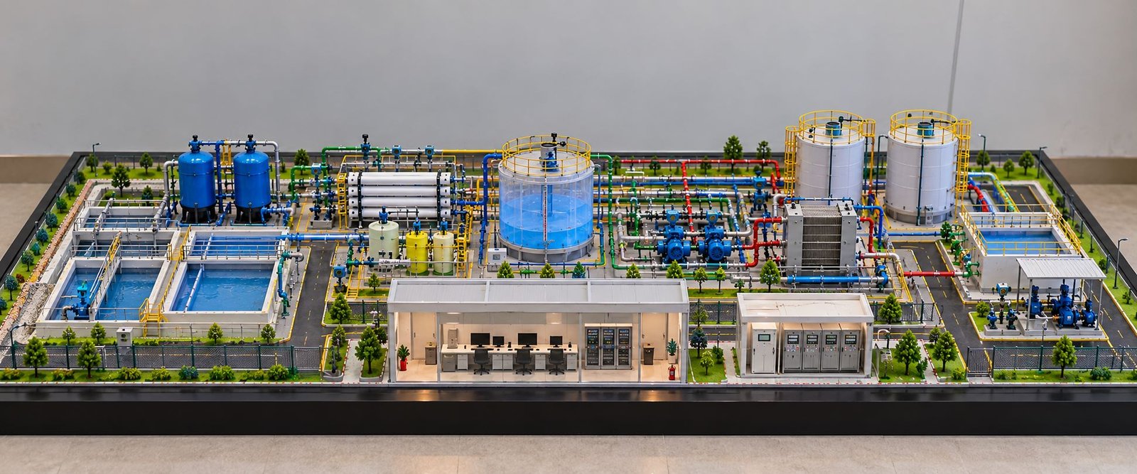
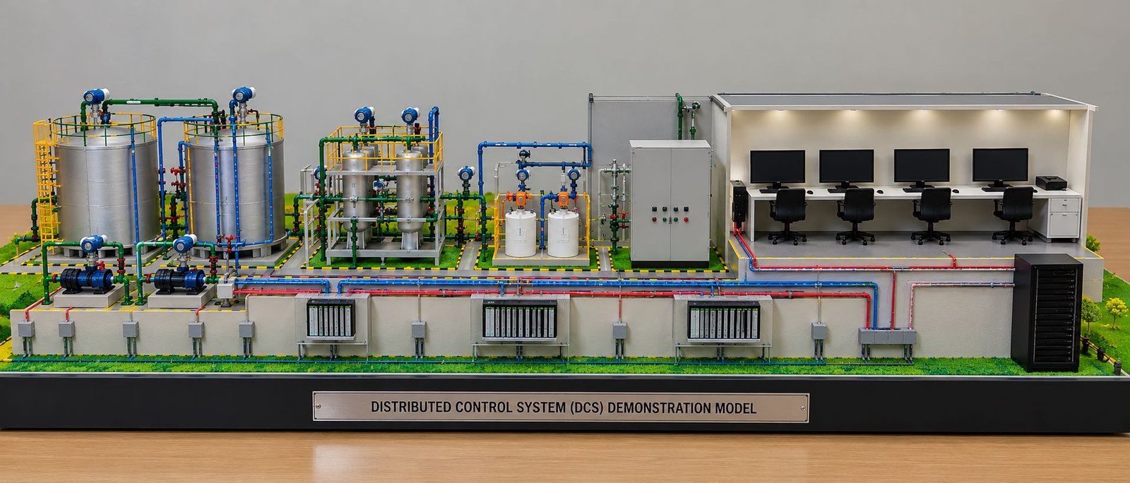
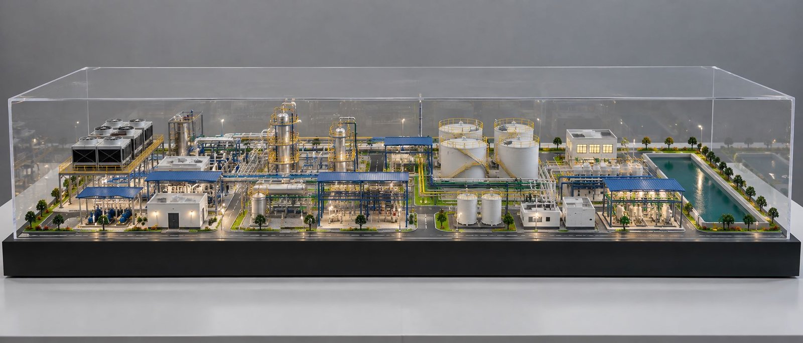
The featured model represents a compact industrial process facility on a wide rectangular base. It includes storage tanks, vertical vessels, horizontal equipment, pumps, mechanical units, pipe racks, multiple piping routes, platforms, ladders, safety railings, process structures, support frames, and other industrial details. Moreover, the wide, low-height arrangement keeps the complete plant layout visible while maintaining a professional presentation.
For engineering presentations, the model illustrates plant arrangement, mechanical equipment positioning, piping and access, and relationships between process systems. Therefore, teams can use it as a practical visual reference during design reviews, client meetings, exhibitions, technical presentations, and project discussions.
What Are Engineering Models for Piping and Mechanical Systems?
Physical Representation of Engineering Systems
An engineering model for piping and mechanical systems provides a scaled physical representation of industrial equipment, piping, mechanical systems, structures, and related plant infrastructure.
Model makers translate engineering information into physical components. For example, they represent equipment with miniature vessels, tanks, pumps, motors, compressors, heat exchangers, columns, pipe racks, platforms, ladders, valves, and piping connections.
As a result, viewers can examine complex plant information closely because multiple systems appear together within one three-dimensional environment.
Combining Mechanical Equipment and Piping
Mechanical equipment rarely operates independently. Pumps connect with piping, vessels receive or discharge process lines, pipe racks carry multiple pipelines, and equipment often requires platforms and access structures.
Therefore, the physical model needs to show these relationships clearly. A detailed engineering model brings mechanical equipment and piping systems together and shows how the components occupy the same plant area.
Supporting Industrial Project Visualization
Engineering models can represent process plants, refineries, chemical facilities, manufacturing plants, power plants, water treatment facilities, oil and gas installations, and other industrial environments.
Meanwhile, the project requirements, selected scale, available engineering information, and overall scope determine the level of model detailing.
Wide and Low-Height Engineering Model Design
Creating a Wide Industrial Layout
The featured model uses a wide rectangular base with a relatively low overall presentation height. This arrangement works particularly well for industrial facilities that contain many components across a large plant area.
The wider base gives equipment, tanks, pumps, pipe racks, and access routes enough visual separation. As a result, viewers can identify individual systems more easily.
Maintaining Clear Equipment Visibility
Industrial plants can look crowded when equipment sits too close together. For this reason, professional model makers maintain suitable spacing between major components.
In addition, the wide layout gives piping routes enough room to pass between equipment while keeping major mechanical units visible from the front and sides.
Presenting the Complete Plant in One View
A wide-format model works particularly well for client presentations. Consequently, viewers can observe the overall arrangement without examining multiple model sections.
The complete industrial system appears as one physical presentation environment.
Mechanical Equipment Detailing
Pumps and Motors
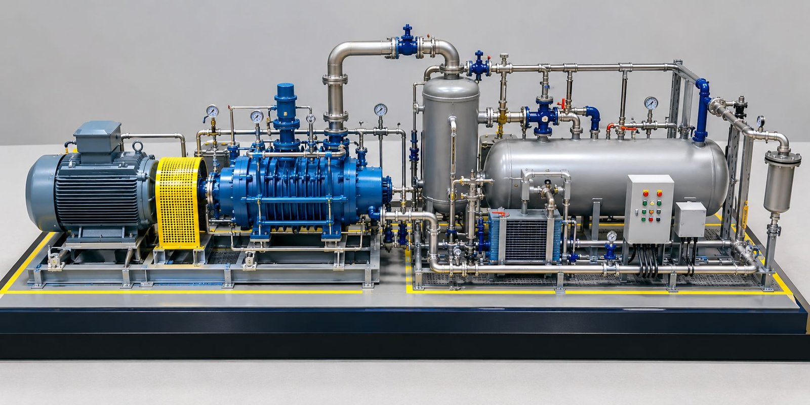
Pumps play an important role in many industrial process systems. Model makers represent pumps with miniature pump bodies, motor housings, coupling sections, mounting bases, and connected piping.
In addition, the motor sits with the pump assembly and can appear as a separate mechanical component. This arrangement helps viewers understand how the motor drives the pump while process piping connects the equipment to the wider plant system.
Pump skids can also include base frames, suction lines, discharge lines, valves, small instruments, and support structures.
Compressors and Mechanical Units
Where the project requires them, model makers can include compressors and other rotating equipment. Similarly, these units can show motor or drive arrangements, base frames, piping connections, and supporting structures.
As a result, this detailing communicates the mechanical side of an industrial process rather than showing only architectural structures.
Heat Exchangers
Model makers can represent heat exchangers as horizontal or vertical mechanical units according to the plant arrangement.
Furthermore, the physical model can show the main shell, connection points, support structures, and associated piping. These details help viewers understand where the equipment fits within the process area.
Pressure Vessels
Vertical and horizontal pressure vessels form important parts of many process facilities.
For this reason, the model can show vessel bodies, support legs, platforms, ladders, top connections, bottom connections, and connected process lines. These details help viewers understand equipment height and its relationship with nearby piping.
Storage Tank Models
Cylindrical Storage Tanks
The featured model includes large cylindrical storage tanks on one side of the plant layout.
These tanks can represent storage or process-related systems according to the project. In addition, their physical detailing can include cylindrical bodies, top covers, access ladders, safety railings, nozzles, piping connections, and surrounding access areas.
Tank Connections
Piping connections around storage tanks play an important role because they show how material enters or leaves the tank system.
For example, small-diameter pipes connect larger process lines with valves, pumps, and other equipment. Model makers carefully position these connections according to the selected model scale.
Tank Safety and Access
The model can also show safety railings and access ladders around tanks. Therefore, these details illustrate how operators can access equipment areas within the industrial facility.
Detailed Piping Systems
Main Process Piping
Piping forms one of the most important elements of an engineering model for piping and mechanical systems.
Main process pipes connect tanks, vessels, pumps, process equipment, and other mechanical units. Moreover, model makers can use different pipe diameters and, where required, different colors to distinguish the routes.
As a result, this visual system makes the flow arrangement easier to understand.
Piping Headers
Large horizontal headers run through the plant and distribute process lines to individual equipment.
The model can show these headers along pipe racks or supporting structures. Meanwhile, smaller branch lines connect the headers with individual equipment.
Branch Piping
Branch pipes connect the main piping network with specific equipment.
These lines can include elbows, tees, reducers, valves, flanges, and other visible components. Although these parts remain miniature, accurate placement gives the model a stronger engineering appearance.
Piping Color Coding
Color coding helps separate different piping systems.
For instance, the model can use different colors for process lines, utility lines, cooling systems, water lines, or other project-specific services. Therefore, the project team can select the exact color scheme according to its presentation requirements.
Pipe Rack Detailing
Multi-Level Pipe Racks
Pipe racks support multiple pipelines and form major features of many industrial plants.
The model can show horizontal and vertical structural members, multiple pipe levels, support brackets, access platforms, and connecting pipe routes.
Pipe Supports
Pipes need proper support instead of appearing to float above the plant. For this reason, model makers place small support structures underneath or alongside the pipelines.
Consequently, these details improve both the visual realism and engineering character of the model.
Connecting Different Plant Areas
A pipe rack can connect several process areas within the same facility. Therefore, it becomes an important visual element for understanding how different equipment groups communicate through piping.
Valves, Flanges, and Small Piping Components
Industrial Valve Representation
Valves form important details within piping systems. Model makers place miniature valves at major connection points, equipment connections, and selected sections of process piping.
Although valves remain small compared with tanks and vessels, they add technical detail to the model.
Flanges and Pipe Connections
The model can show flanges at equipment and piping connection points where the project requires them.
Similarly, elbows and tees demonstrate changes in piping direction and branching arrangements.
Small-Bore Piping
Model makers can add small-bore piping around larger equipment when the project requires additional detailing.
These lines can represent, for example, instrument connections, drains, vents, utility connections, or other supporting systems.
Platforms, Ladders, and Access Structures
Equipment Platforms
Industrial equipment often requires platforms for inspection, operation, and maintenance.
The model can show platforms around vertical vessels, columns, and process structures. As a result, these platforms provide a realistic representation of equipment access.
Stairways and Ladders
Ladders and stairways connect different levels of the plant.
In addition, their inclusion demonstrates how operators access elevated equipment areas. Safety railings can also run along platform edges and stair structures.
Safety Railings
Yellow safety railings create a strong industrial visual identity while also representing safety barriers around elevated working areas.
Therefore, these details become particularly valuable when the plant contains multiple vertical levels.
Process Columns and Vertical Equipment
Tall Process Columns
Vertical columns often become some of the tallest components within a process plant.
The featured model includes tall cylindrical equipment with multiple access levels and railings. Consequently, these elements add vertical variation to the otherwise wide and low-height model.
Multiple Access Levels
Platforms around tall equipment can sit at different elevations.
This arrangement, in turn, shows how operators and maintenance teams can access different sections of the equipment.
Connecting Column Piping
Piping connects the upper and lower portions of columns with nearby vessels, headers, and process equipment.
As a result, these connections demonstrate the relationship between vertical equipment and the horizontal piping network.
Mechanical Skids and Equipment Bases
Equipment Mounting
Mechanical equipment generally needs a stable base or support structure.
The model can show pumps, motors, horizontal vessels, and other units mounted on miniature concrete or steel bases.
Skid-Mounted Equipment
Some mechanical systems use compact skids that combine equipment, piping, valves, and supporting frames.
Therefore, the model can reproduce these arrangements to provide a detailed representation of packaged mechanical systems.
Equipment Identification
Where required, small identification plates or labels can help viewers recognize major equipment during technical presentations. In this way, the model becomes easier to understand during project discussions.
Industrial Structural Framework
Steel Structures
Industrial plants frequently use structural steel frameworks to support equipment, piping, platforms, and roofed areas.
The model can include columns, beams, cross-members, platforms, and support frames.
Equipment Support Structures
Heavy equipment may require dedicated support structures. Accordingly, model makers can place these structures beneath vessels, piping, tanks, or process units.
Relationship Between Structure and Equipment
The physical model helps viewers understand how structural systems support mechanical equipment and piping.
In contrast, this relationship can become difficult to visualize when separate engineering disciplines appear only in individual drawings.
Instrumentation and Control Details
Instrument Connections
Instrumentation adds another layer of detail to an engineering model.
The model can show small instruments connected to process equipment and piping. Depending on the required level of detail, these components can include gauges, transmitters, instrument lines, junction boxes, and control-related elements.
Showing Process Monitoring
These miniature components demonstrate that the plant includes monitoring and control systems alongside mechanical equipment and piping.
As a result, viewers can understand more of the complete engineering environment.
Maintaining Appropriate Scale
Instrumentation should maintain a proportional relationship with the selected model scale.
However, excessive miniature detailing can make the model look crowded. Therefore, the model should prioritize important instruments and connections.
Utility and Supporting Systems
Utility Piping
Industrial plants require supporting utility systems alongside primary process piping.
The model can include utility pipelines running through pipe racks or connecting to individual equipment. In addition, cooling and service systems, compressed-air lines, and other project-specific services can appear when the engineering information requires them.
Keeping Systems Visually Organized
Clear routing and suitable spacing help viewers distinguish major systems.
Especially when several piping networks occupy the same plant area, this organization becomes important.
Roads, Walkways, and Plant Circulation
Internal Plant Roads
Although mechanical and piping systems remain the main focus, internal roads provide important site context.
The model can show roads around major equipment zones, storage areas, and plant buildings.
Operator Walkways
Walkways and access routes demonstrate how personnel move between different areas of the facility.
Furthermore, these routes provide useful context around mechanical and piping systems.
Relationship With Equipment
The model allows viewers to understand how equipment placement affects circulation.
As a result, large vessels, tanks, pumps, and pipe racks appear together with surrounding access routes, creating a clearer picture of the plant environment.
Industrial Buildings and Covered Areas
Equipment Shelters
The featured model includes covered structural areas that can represent equipment shelters or process support structures.
These areas can contain mechanical equipment, piping, platforms, and other industrial components. Moreover, corrugated or industrial-style roof structures can add realism.
Integration With the Plant
Covered structures should maintain an integrated relationship with nearby piping and mechanical systems.
Therefore, this approach keeps the overall plant arrangement visually coherent.
Importance of Scale in Engineering Models
Selecting the Correct Scale
Scale plays a critical role in engineering model making.
The selected scale needs to keep important mechanical components, piping, valves, equipment connections, and structural details visible while maintaining a practical overall model size.
Balancing Detail and Size
A very small scale can make piping and mechanical details difficult to reproduce. On the other hand, an extremely large scale can make the complete plant difficult to display.
Therefore, the model maker must balance physical size with the required level of engineering detail.
Materials and Fabrication Techniques
Laser Cutting
Laser cutting supports the production of precise structural components, platforms, brackets, panels, and other model parts.
As a result, model makers can achieve consistent shapes and detailed fabrication.
3D Printing
3D printing helps produce complex mechanical components, equipment housings, fittings, valves, custom supports, and other detailed elements.
In addition, this technique can support components that require complex shapes.
Hand Assembly and Finishing
Many engineering models require careful manual assembly after fabrication.
Model makers position and finish small pipes, railings, equipment parts, ladders, and structural components by hand.
Ultimately, the combination of digital fabrication and hand craftsmanship contributes to the professional appearance of the finished model.
Color Coding and Visual Identification
Differentiating Systems
Color helps viewers distinguish different piping and mechanical systems.
A planned color scheme can separate major process lines from utility systems while also highlighting important equipment.
Maintaining Professional Appearance
The model should maintain consistent colors throughout the presentation.
Otherwise, random or excessive colors can reduce clarity. Therefore, the team should use color as an information tool rather than simply as decoration.
Lighting for Engineering Models
Equipment and Area Lighting
LED lighting can add another presentation layer to an engineering model.
Model makers can add small lights to highlight process equipment, buildings, pathways, or important plant areas.
Presentation During Exhibitions
Illuminated models can work particularly well for exhibitions, corporate presentations, and evening displays.
However, lighting should support the engineering information rather than distract viewers from equipment and piping details.
Engineering Models for Client Presentations
Making Technical Information Easier to Understand
A detailed engineering model allows clients to see equipment and piping together.
Instead of reviewing multiple drawings, clients can observe the plant arrangement and discuss specific areas directly on the model. As a result, technical information becomes easier to communicate.
Supporting Project Discussions
Engineers can point to pumps, motors, vessels, pipe racks, pipelines, tanks, platforms, and other equipment while explaining the project.
In this way, the model creates a common visual reference for everyone involved.
Supporting EPC and Industrial Projects
EPC contractors, engineering consultants, plant designers, project managers, and industrial companies can use these models for project communication and presentation purposes.
Engineering Models for Design Review
Reviewing Equipment Placement
Physical models support discussions about the relative location of equipment.
For example, teams can examine pumps, vessels, tanks, and process units in relation to each other.
Reviewing Piping Routes
Physical piping routes make technical discussions easier.
Furthermore, teams can follow major lines through pipe racks and observe how they connect different equipment groups.
Reviewing Access and Maintenance Areas
Teams can also review platforms, ladders, walkways, and open spaces as part of the overall plant arrangement.
Consequently, the physical model provides a broader reference for design review.
Engineering Models for Project Visualization
A professional engineering model for piping and mechanical systems provides a physical visualization of how mechanical systems, piping, structures, circulation, and supporting infrastructure work together.
In particular, the wide-format arrangement proves useful for projects with many interconnected systems. Viewers can move around the model and examine the plant from different sides.
Consequently, engineering information becomes easier to communicate to both technical and non-technical stakeholders.
Conclusion
Engineering Models for Piping and Mechanical Systems offer a practical way to visualize complex industrial facilities in three dimensions.
By combining pumps, motors, tanks, vessels, process equipment, piping, valves, pipe racks, platforms, ladders, structural frames, instrumentation, access areas, and supporting infrastructure, a physical model communicates a large amount of engineering information within one presentation.
The featured industrial model demonstrates how a wide rectangular base can accommodate multiple mechanical and piping systems while maintaining a relatively low overall height. Storage tanks occupy dedicated areas, while pumps, motors, vessels, and process equipment sit across the central plant. Pipe racks carry multiple pipelines, while vertical equipment adds height and structure to the facility.
Furthermore, details such as valves, pipe supports, platforms, ladders, safety railings, equipment bases, structural frames, and access routes enhance the technical character of the model. In addition, suitable color coding and optional LED lighting can strengthen the physical representation for engineering presentations.
Professional engineering model making can support EPC contractors, industrial consultants, plant designers, project managers, architects, mechanical engineers, piping engineers, and developers. Therefore, the model offers a shared physical reference for discussing equipment placement, piping routes, plant layout, access, circulation, and overall project organization.
Overall, a detailed physical engineering model transforms complex piping and mechanical information into an understandable three-dimensional environment. Accurate scale, detailed equipment, realistic piping, mechanical components, structural supports, and professional finishing work together to communicate the engineering concept and overall industrial project vision.