Machine Cutaway Engineering Models: Detailed Guide to Industrial Sectional Models
Machine cutaway engineering models provide a practical way to understand complex machines, mechanical assemblies and engineering systems. Unlike regular machine models that show only the outside appearance, a cutaway model also shows important internal parts through selected openings. As a result, these models are useful for technical presentations, engineering education, product demonstrations, exhibitions, training programs and industrial communication.
A professionally made machine cutaway engineering model can show shafts, bearings, gears, impellers, pistons, cylinders, valves, couplings, motors, housings, lubrication systems and other mechanical parts. In addition, each component can be made at a suitable scale. This helps viewers understand how the machine is assembled and how different parts work together.
For industries, engineering companies, educational institutions and manufacturers, a physical cutaway model can explain technical information more clearly than drawings alone. Moreover, it gives viewers a three-dimensional understanding of the machine while keeping the important details of the original design.
What Is a Machine Cutaway Engineering Model?
A machine cutaway engineering model is a physical scale model in which selected portions of a machine are removed or opened to show its internal components. The outer structure remains visible, while the open sections provide a clear view of the internal mechanism.
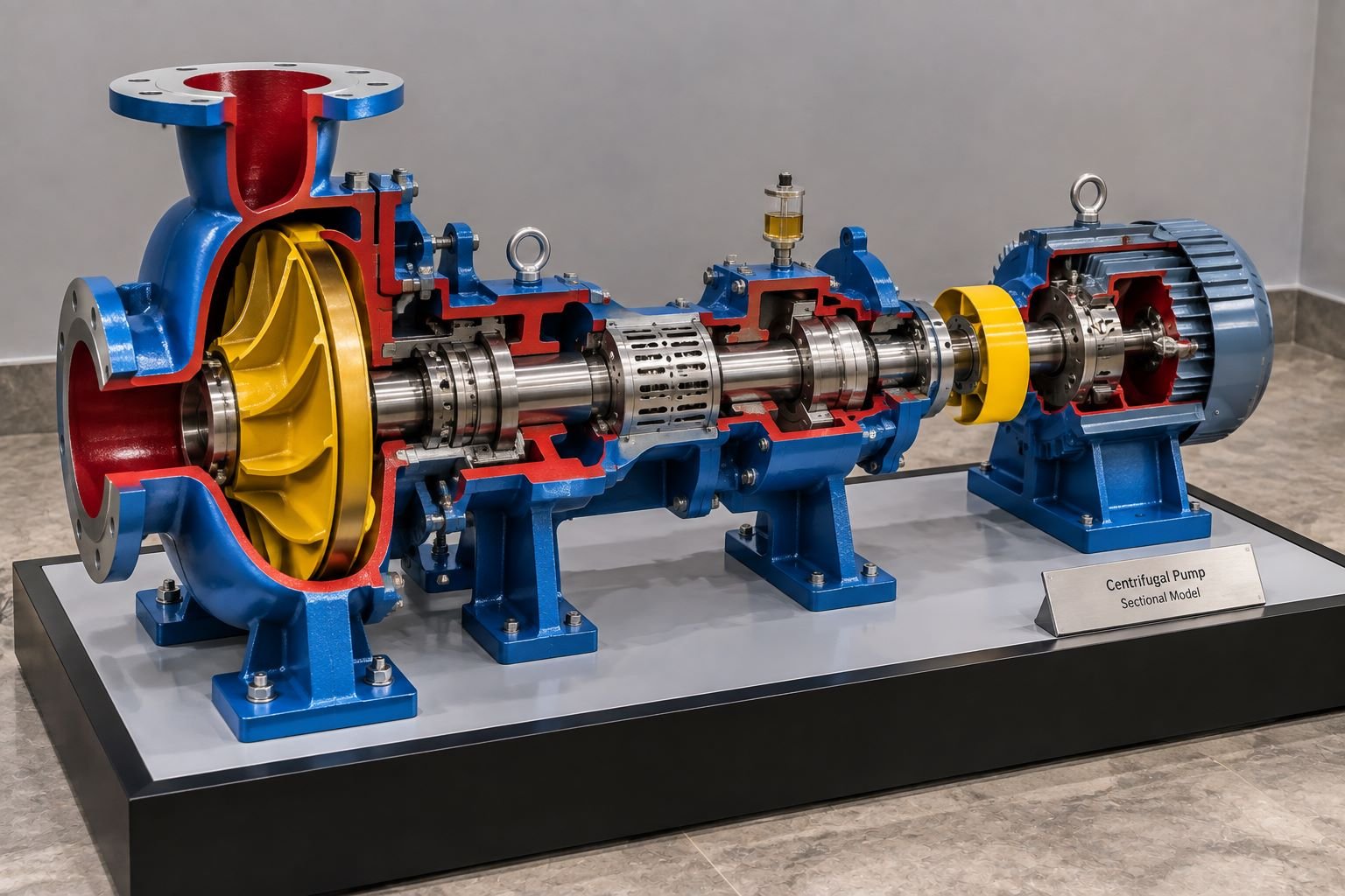
For example, a cutaway centrifugal pump model can show the pump casing, impeller, shaft, bearings, mechanical seal, coupling and motor arrangement in one physical model. Similarly, an engine cutaway model can reveal pistons, connecting rods, crankshaft, cylinder block, valves and other internal components.
The purpose is not simply to make a smaller version of a machine. Instead, the model focuses on engineering visualization, internal detailing, component relationships and mechanical understanding.
Therefore, a good machine cutaway model should have three important aspects:
- Accurate external form
- Clear internal component visibility
- Professional physical model finishing
Together, these features make the model suitable for technical demonstrations and professional presentations.
Why Machine Cutaway Models Are Important for Engineering
Engineering machines often contain many components inside their housings. A person can see the outside of a pump, gearbox, engine, compressor or turbine. However, understanding the internal arrangement can be difficult without technical drawings or digital visualization.
Therefore, a machine cutaway model exposes the internal construction and makes the machine easier to understand.
The model can help explain:
- How internal components are arranged
- How different components connect
- The location of shafts and bearings
- How gears interact
- How fluids move through equipment
- How mechanical parts are supported
- How different assemblies fit together
- How a machine works internally
In educational environments, physical models can support practical learning. As a result, students can observe the relationship between components instead of relying only on two-dimensional diagrams.
For industrial companies, the same model can also be used for product demonstrations, customer presentations, exhibitions, training sessions and technical discussions.
Types of Machine Cutaway Engineering Models
Different machines require different cutaway approaches. Therefore, the open section depends on the purpose of the model and the components that need to remain visible.
Centrifugal Pump Cutaway Models
A centrifugal pump is a useful application for a sectional engineering model because many important components are located inside the casing.
A detailed pump cutaway model can show the impeller, shaft, bearings, mechanical seal, casing, suction inlet, discharge outlet, coupling and motor. In addition, the casing can be partly removed to expose the impeller and shaft arrangement.
Different colors can also be applied to individual components. In this way, viewers can identify the internal parts more easily.
As a result, a professional centrifugal pump cutaway model can be used for engineering education, product demonstrations, industrial training and technical exhibitions.
Engine Cutaway Engineering Models
Engine cutaway models are often used to explain internal mechanical movement.
A sectional engine model may reveal:
- Cylinder block
- Pistons
- Connecting rods
- Crankshaft
- Valves
- Camshaft
- Combustion chamber
- Flywheel
- Lubrication passages
- Cooling passages
The sectional design allows viewers to understand how the internal components relate to each other. Moreover, the open section makes the mechanical arrangement easier to explain.
For educational institutions and automotive companies, an engine cutaway model can provide a useful physical representation of mechanical operation.
Gearbox Cutaway Models
Gearboxes contain multiple gears, shafts, bearings and housings. However, these components are difficult to understand when the gearbox remains completely enclosed.
A gearbox cutaway model exposes selected sections of the housing. Therefore, the gear arrangement becomes visible.
The model can demonstrate:
- Gear relationships
- Input and output shafts
- Bearing positions
- Gear reduction
- Housing structure
- Shaft alignment
- Different gear stages
Furthermore, a well-designed gearbox engineering model can be particularly useful for mechanical engineering training and product presentations.
Compressor Cutaway Models
Industrial compressors contain internal components that require careful representation.
Depending on the compressor type, the model may show cylinders, pistons, crankshafts, valves, connecting rods, pressure chambers, shafts, bearings and other mechanical elements.
Therefore, a cutaway compressor model can help viewers understand the relationship between the external housing and internal mechanical components.
Turbine Cutaway Models
Turbines contain rotating components and internal flow passages that can be difficult to visualize from external photographs.
A turbine cutaway model can expose selected sections to demonstrate the arrangement of blades, rotor, shaft, casing, bearings and other components.
As a result, these models can support engineering presentations and technical training.
Design Process for Machine Cutaway Engineering Models
Creating a professional physical model requires more than simply reducing the dimensions of an existing machine.
First, the design team needs to understand the original machine. Then, the team identifies which components should remain visible and which areas should be opened.
In this way, the final model can maintain the appearance of the original equipment while also showing the important internal parts.
Reviewing Engineering Drawings
The process usually begins with technical drawings, CAD files, photographs, dimensions, assembly drawings or other reference information.
The model maker studies the available information to identify:
- Overall dimensions
- Component relationships
- Internal mechanisms
- Sectional areas
- Mounting arrangements
- Material appearance
- Required scale
Therefore, this information becomes the foundation for the physical engineering model.
Selecting the Correct Cutaway Section
The sectional opening is one of the most important design decisions.
If too little of the machine is opened, the internal components may still be difficult to see. On the other hand, if too much is removed, the model may lose the appearance and structural character of the original machine.
Therefore, the cutaway area should be selected according to the purpose of the model.
For example, for a pump, exposing the casing and impeller may be the priority. In contrast, for an engine, exposing the cylinder, piston, connecting rod and crankshaft may provide more educational value.
Scale Selection
The scale determines how much detail can be incorporated into the model.
For this reason, scale selection should consider both the machine size and the intended use.
Common scale considerations include:
- Available display space
- Size of the original machine
- Required component visibility
- Level of engineering detail
- Transportation requirements
- Exhibition requirements
A larger model can incorporate more physical details. However, a smaller model requires careful simplification.
Ultimately, the goal is to maintain the important engineering characteristics without making the model unnecessarily large.
Materials Used in Machine Cutaway Models
Professional engineering models can use different materials depending on the required finish, size, strength and level of detail.
Common materials include acrylic, MDF, foam board, resin, plastics, metal components, 3D-printed parts, transparent sheets and fabricated sections.
Acrylic and Transparent Components
Transparent acrylic can be useful when a designer wants to reveal internal areas without completely removing the external structure.
For example, transparent sections can represent protective covers or inspection areas.
In this way, viewers can see internal components while still understanding the overall external form.
3D Printed Components
3D printing is particularly useful for complex mechanical components. For example, it can produce detailed:
- Gear profiles
- Housings
- Impellers
- Brackets
- Small mechanical parts
- Custom connectors
- Complex internal structures
Moreover, 3D printing allows model makers to reproduce components that would be difficult to fabricate manually.
As a result, it has become a useful method for producing detailed parts in modern engineering model making.
Metal Components
Small metal shafts, bolts, rods, bearings, screws and other components can add realism to a machine cutaway engineering model.
In addition, these details become especially important in professional exhibition models where viewers may inspect the model from a short distance.
Internal Detailing in Engineering Cutaway Models
Internal detailing separates a professional sectional model from a simple miniature machine.
The visible internal components should have clear relationships and suitable proportions. For example, a gearbox should not simply contain random gears. Instead, the gears should correspond to the intended mechanical arrangement.
Similarly, an engine model should represent the relationship between the piston, connecting rod, crankshaft and cylinder.
Shafts and Bearings
Shafts should line up correctly with the surrounding components. Bearings can be represented using miniature rings and housings.
As a result, these details help communicate how the machine is assembled.
Gears
Gears require accurate proportions and spacing.
Different gear sizes can visually communicate different transmission stages. Moreover, contrasting finishes can make individual gear sets easier to identify.
Bolts and Fasteners
Small bolts and fasteners may appear to be minor details. However, they can add significant realism to an industrial model.
They can be found around:
- Flanges
- Covers
- Housings
- Base plates
- Inspection panels
- Mechanical joints
In addition, these small components help create a more realistic physical engineering model.
Internal Passages
For pumps, compressors, valves and fluid-handling equipment, internal passages can be an important part of the model.
Furthermore, these passages can show how fluid moves through the machine. Therefore, viewers can understand the internal flow arrangement more easily.
Color Coding in Machine Cutaway Models
Color can make a technical model easier to understand.
However, color should be applied with purpose rather than randomly.
For example, a model may use separate colors for:
- Main housing
- Rotating components
- Internal sections
- Shafts
- Fluid passages
- Electrical components
- Structural supports
In addition, a contrasting sectional surface can make the cutaway area immediately visible.
The final color scheme should still look professional and should relate to the original equipment wherever practical.
Physical Model Finishing and Presentation
A physical machine model should look like a professionally manufactured display piece rather than a rough prototype.
Finishing may include surface preparation, sanding, painting, edge finishing, polishing, component detailing and final assembly.
After fabrication, the model can also be mounted on a dedicated baseboard or presentation platform.
A clean base provides several advantages:
- Better stability
- Easier transportation
- Professional presentation
- Protection for delicate components
- Better visibility during exhibitions
For large engineering models, the base can also include mounting points and lighting.
Baseboard Design for Engineering Models
The baseboard should match the dimensions and proportions of the machine.
A rectangular base is often suitable for industrial and engineering models because it provides a clean presentation area.
The baseboard can include:
- Raised platform
- Recessed display area
- Acrylic cover
- LED lighting
- Machine identification
- Technical labeling
- Company branding
However, the design should remain clean. Excessive decoration can distract viewers from the engineering model itself.
Lighting for Machine Cutaway Engineering Models
Lighting can improve the visibility of internal components.
For example, small LED lights can be positioned around important areas of the model to highlight the cutaway section.
Lighting can emphasize:
- Gear assemblies
- Pump impellers
- Engine cylinders
- Control components
- Internal passages
- Mechanical assemblies
Therefore, the lighting should support the technical presentation rather than overpower it.
For exhibition models, carefully integrated lighting can make internal details easier to observe from different viewing angles.
Machine Cutaway Models for Engineering Education
Educational institutions can use cutaway engineering models to explain mechanical concepts in a practical way.
Students can observe how components fit together and how different assemblies interact.
As a result, a physical model can support lessons related to:
- Mechanical engineering
- Manufacturing
- Fluid mechanics
- Automotive engineering
- Industrial machinery
- Power systems
- Machine design
- Production engineering
Instead of looking only at a diagram, students can inspect the actual three-dimensional relationship between components.
Industrial Training Applications
Industries can use machine cutaway models for employee training.
Training teams can explain equipment construction without opening an operational machine. This can be especially useful for large or complicated industrial equipment where accessing internal components is difficult.
Therefore, a sectional model can demonstrate equipment structure in a controlled environment.
Moreover, the model can remain permanently available in a training room. As a result, there is less need to repeatedly dismantle operational equipment for basic demonstrations.
Machine Cutaway Models for Product Presentations
Manufacturers can use sectional models to explain products to customers, consultants, engineers and project teams.
A customer may understand a machine’s external appearance from a photograph. However, the internal design can be difficult to communicate through photographs alone.
In contrast, a cutaway model provides a physical demonstration. Sales and technical teams can point directly to specific components during discussions.
This makes the model useful for:
- Product launches
- Client meetings
- Technical presentations
- Trade exhibitions
- Dealer training
- Factory visitor demonstrations
- Engineering seminars
Therefore, a sectional model can support both technical communication and product presentation.
Engineering Models for Exhibitions and Trade Shows
Exhibitions require models that attract attention while also communicating information clearly.
A large machine cutaway model can become an important display element at an industrial exhibition.
The model can be placed on a professional display counter or custom pedestal. In addition, a clear acrylic enclosure can protect the model while allowing visitors to observe the internal components.
For exhibition use, durability and transportation also become important considerations.
Therefore, the model should have a strong base, secure components and suitable protective packaging.
Accuracy and Detailing in Sectional Models
Accuracy is important when producing a machine cutaway engineering model.
The model does not always need to reproduce every microscopic feature of the original machine. Instead, it should accurately represent the components that matter for the intended purpose.
For example, a training model may prioritize functional relationships. On the other hand, an exhibition model may emphasize visual detailing and presentation quality.
The right balance depends on the application. As a result, important areas should receive greater attention than hidden or visually insignificant features.
Combining 3D Printing With Traditional Model Making
Modern machine model making can combine several fabrication methods.
3D printing can produce complex components, while CNC cutting, laser cutting, acrylic fabrication, manual assembly and painting can complete the model.
As a result, this combined approach allows model makers to produce detailed physical engineering models efficiently.
For example, a complicated impeller can be 3D printed, while the base and larger housing sections can be fabricated separately.
After fabrication, individual components can be assembled and finished to create a complete physical model.
Quality Control of Machine Cutaway Models
Before delivery, the model should go through a detailed quality inspection.
The inspection can include:
- Dimensional checking
- Component alignment
- Sectional accuracy
- Surface quality
- Paint finishing
- Assembly strength
- Base stability
- Lighting operation
- Internal visibility
- Packaging readiness
Finally, a complete inspection helps ensure that the finished model represents the intended engineering design.
Choosing a Professional Machine Model Making Company
Selecting the right model-making company is important when the project requires engineering accuracy and detailed finishing.
Before starting the project, clients should provide available drawings, CAD files, photographs, dimensions, reference samples and the intended purpose of the model.
Based on this information, a professional engineering model making company can determine the appropriate scale, materials, fabrication method, detailing level and presentation format.
The company should also understand how to balance technical accuracy with clear visual communication.
Furthermore, this becomes especially important when the model will be used for client presentations, exhibitions, training or educational purposes.
Benefits of a Physical Machine Cutaway Model
A physical sectional model provides several practical benefits.
Better Technical Understanding
The model makes internal components visible and easier to understand.
Stronger Presentations
A physical model can provide a clear demonstration during technical meetings.
Practical Learning
Students and trainees can examine the relationship between components in three dimensions.
Improved Product Communication
Manufacturers can demonstrate internal construction without dismantling actual equipment.
Long-Term Display Value
A professionally finished model can remain available for repeated demonstrations and exhibitions.
Overall, these benefits make physical machine cutaway models useful for education, industrial communication, training and professional presentations.
Conclusion
Machine Cutaway Engineering Models provide an effective way to represent complex mechanical equipment in a clear three-dimensional format. By exposing selected internal components, these models help viewers understand machine construction, component relationships and engineering mechanisms.
From centrifugal pumps and engines to gearboxes, compressors, turbines, industrial machinery and mechanical assemblies, sectional models can be developed for a wide range of engineering applications.
The quality of a physical cutaway model depends on accurate reference information, appropriate scale selection, careful sectional design, detailed fabrication, realistic finishing and professional presentation.
Moreover, modern techniques such as 3D printing can improve the production of complex components. At the same time, traditional fabrication methods can provide strong structural support and good finishing.
For engineering companies, manufacturers, educational institutions, EPC organizations and industrial exhibitors, a professionally developed machine cutaway engineering model can turn complicated technical information into an easy-to-understand physical presentation.
Finally, whether the requirement is an educational machine model, industrial equipment model, mechanical cutaway, product demonstration model or exhibition display, careful engineering model making can provide a detailed and practical representation of the original equipment.