Oil Refinery Model: Detailed 3D Industrial Scale Model
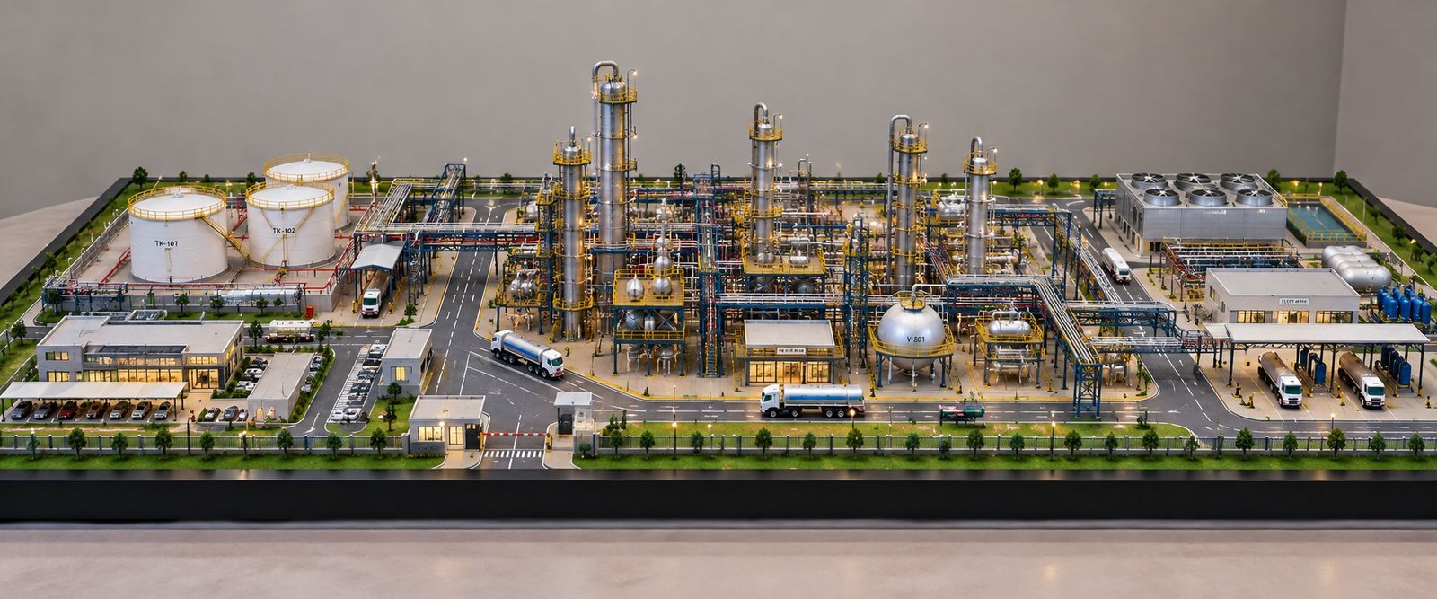
An Oil Refinery Model is a detailed physical representation of a refinery complex, showing the arrangement of process units, storage facilities, piping systems, utility areas, roads, safety areas, and supporting infrastructure in one 3D view. A well-planned oil refinery scale model can show the relationship between the refinery sections while simplifying the large and technically complex industrial site.
Unlike a simple industrial display, the detailed refinery model focuses on the actual character of the petroleum processing facility. The tall process columns, cylindrical storage tanks, pipe racks, vessels, heaters, cooling equipment, loading areas, control buildings, roads, utilities, and supporting infrastructure work together to create a realistic representation of the complete plant.
Understanding an Oil Refinery Through a Physical Model
An oil refinery receives crude oil and processes it through a series of physical separation and chemical conversion steps to produce useful petroleum products. The exact configuration varies according to the crude feed, product requirements, refinery capacity, and process technology.
The crude distillation unit, commonly called the CDU, is a major starting point of a typical refinery. It separates the crude oil into fractions based mainly on the differences in boiling ranges. The fractions can include naphtha, kerosene-range material, gas oils, and heavier residue, which then move towards the additional processing units.
A physical petroleum refinery scale model can represent the different process areas as separate sections while maintaining the relationship within the complete refinery layout. It is useful for the presentation where a two-dimensional drawing cannot communicate the plant arrangement as clearly.
Detailed Refinery Plant Layout
The most important aspect of the industrial refinery model is the site layout.
A refinery can occupy a large area and contain a numerous interconnected facilities. Therefore, the model needs to show the position of the individual sections across the site. The process area may occupy the central portion, while the storage tanks, utilities, administrative buildings, roads, loading areas, and other supporting facilities can be arranged around it.
The rectangular layout of the refinery scale model also helps to create a broad, easy-to-view presentation. Instead of concentrating the plant into a small vertical composition, the model can spread the refinery horizontally across the wide base. It is particularly effective for the feature image as the viewer can see the complete industrial facility from one perspective.
A Well-Designed Refinery Plant Model Can Include:
- Crude oil receiving areas
- Crude distillation units
- Vacuum distillation areas
- Process columns
- Heat exchangers
- Fired heaters
- Hydroprocessing units
- Catalytic processing areas
- Storage tanks
- LPG storage vessels
- Pipe racks
- Pump areas
- Cooling systems
- Utility facilities
- Control buildings
- Product loading areas
- Internal roads
- Security and boundary areas
The exact units depend on the refinery configuration. Typical refinery process diagrams can contain a number of separate processing and treatment sections, which explains why a physical model can become highly detailed.
Crude Distillation Unit in a Refinery Model
The Crude Distillation Unit Model is one of the most recognizable sections of an oil refinery.
Crude Distillation Unit
In the real refinery, the crude oil is heated and separated into different fractions according to the boiling range. A typical CDU includes the equipment such as desalter, furnace, heat-exchanger network, distillation column, and associated side systems.
In an oil refinery scale model, the CDU can become the visual centre of the process area. The tall distillation columns immediately communicate the industrial character of the facility. Around the columns, the smaller vessels, horizontal piping, platforms, ladders, structural supports, valves, and connecting pipe racks create the dense appearance of the refinery processing areas.
The difference in the equipment height is also important. The large columns can rise above the surrounding equipment, while the smaller vessels and horizontal units occupy the lower levels. This variation creates the depth, and the 3D refinery model becomes easier to understand.
Distillation Columns and Process Towers
Tall columns are among the most important visual elements of a petroleum refinery model.
Distillation towers are used to separate the hydrocarbon streams into different fractions. Depending on the refinery process, the site can contain the atmospheric distillation columns, vacuum columns, strippers, fractionators, and other process towers.
A physical model should not depict the tower as an isolated cylinder, as their surrounding platforms, ladders, pipe connections, structural supports, overhead lines, and equipment help to communicate how they belong to the larger process system.
Different tower heights can also represent the different process sections. It provides the realistic industrial skyline while keeping the overall model layout horizontal.
Storage Tanks and Oil Storage Areas
Large storage tanks are another defining feature of an oil refinery model.
Refineries require the storage facilities for crude oil, intermediate streams, and finished products. Typical storage tanks are generally large cylindrical structures, while the LPG and other pressurized products can use the different vessel forms.
Oil Storage Tank Model
A detailed oil storage tank model can therefore include the multiple tank sizes inside the dedicated tank farm. The tanks can be arranged in the rows with the access roads, containment areas, connecting pipelines, and safety clearances.
From the presentation perspective, the tank farms provide the strong contrast to the dense process area. The process section may contain tall towers and complex pipework, while the tank farm creates the more open geometric arrangement.
This difference makes the complete refinery scale model visually balanced.
Refinery Pipe Racks and Piping Systems
Piping is one of the most important details in an industrial plant scale model.
A refinery contains extensive networks connecting the process units, storage areas, utility systems, and loading facilities. On a physical model, these connections can be represented through the horizontal and vertical pipe runs.
Pipe Racks and Piping Details
The pipe racks are particularly important because they provide the clear visual connection between the different refinery sections. A well-detailed refinery piping model can show the multiple levels of the pipes running through the plant, supported by the structural frames.
Small details such as bends, vertical drops, supports, platforms, valves, and equipment connections can make a major difference to the appearance of the finished model.
Engineering scale models have historically been used to study plant layouts and piping arrangements, including the valves, ladders, floor grating, and other details.
Process Equipment and Industrial Detailing
A refinery is not made only of towers and tanks.
Between the major units, there are many smaller pieces of process equipment. These can include the separators, heat exchangers, pumps, vessels, furnaces, compressors, air coolers, and associated support structures.
Including these elements gives the oil refinery physical model a more complete appearance.
Equipment Relationships
For example, a heat-exchanger area can be placed below or beside a larger process column. The small vessels can be connected through the piping. The pumps can be positioned close to the process equipment. The platforms can provide the access around the elevated equipment.
These relationships help the viewer understand that every part of the refinery has the place within the overall plant arrangement.
Vacuum Distillation and Secondary Processing
After the atmospheric distillation, the heavier fractions can move into additional processing sections.
A Vacuum Distillation Unit, or VDU, is used to further separate the heavier material under the reduced pressure. Other refinery configurations may include the hydrotreaters, catalytic reformers, fluid catalytic cracking units, hydrocrackers, alkylation units, isomerization units, gas treating facilities, and blending areas.
A detailed refinery plant scale model can represent these areas as separate process blocks while keeping the connections between them visible.
This is one reason refinery models can be much more detailed than the ordinary factory models. A factory building may focus on the building envelope and production floor, while an oil refinery contains the large collection of the interconnected outdoor process equipment.
Oil Refinery Utility Areas
A refinery also depends on the supporting utility systems.
The steam, cooling water, electrical power, compressed air, water treatment, wastewater treatment, and other services support the main process units. The exact arrangement depends on the refinery design.
In a physical oil and gas refinery model, these supporting areas can be represented as smaller buildings, utility equipment, cooling units, pipe networks, tanks, and service roads.
Although these sections may not be the tallest elements of the refinery, they contribute to the completeness of the overall plant.
A detailed model therefore does not focus only on the most impressive towers. It also represents the supporting infrastructure that makes the refinery site look like the functioning industrial complex.
Control Building and Administration Area
A refinery also requires the buildings for the control, management, operations, security, and other supporting functions.
Control Building
The control building is particularly important because it represents the point from which the process operations can be monitored and managed.
In a refinery model making project, the control building can be positioned near the process area while being visually distinct from the heavy process equipment. The administration buildings, security cabins, parking areas, and staff facilities can also be included where appropriate.
This creates a complete industrial campus rather than a collection of the isolated process units.
Roads and Internal Transportation
Internal roads play an important role in the visual structure of a refinery.
Large industrial sites require the routes for the maintenance vehicles, emergency access, tankers, service vehicles, and other transportation. In a physical model, these roads help divide the refinery into the recognizable zones.
A detailed industrial scale model can show the main roads around the process area, smaller service roads between the units, tanker movement areas, parking spaces, and loading zones.
Miniature vehicles can further communicate the scale of the facility. However, they should remain secondary to the refinery itself so that the main focus stays on the industrial plant.
Loading and Unloading Areas
Oil refineries need the systems for receiving the raw materials and dispatching the products.
Depending on the facility, the loading areas may include the road tanker bays, pipeline connections, rail facilities, marine terminals, or other transportation infrastructure.
A petroleum refinery model can include these zones at the edge of the site. Their location helps explain how the material moves into and out of the refinery.
For a presentation model, these areas are especially useful because they show that the refinery is connected to the wider logistics network.
Safety Zones and Boundary Planning
Safety is an essential consideration in the refinery planning.
The physical model can visually distinguish the process areas, storage zones, roads, buildings, and the perimeter areas. Clear separation between the different sections helps to communicate the scale and the organization of the facility.
The boundary walls, security gates, access roads, emergency routes, green zones, designated open areas can add further realism.
The aim is not simply to fill every part of the base with the equipment. The open space is also important because the real industrial facilities require the access, movement, separation, and safety clearances.
Flare Stack and Refinery Skyline
The flare stack is another recognizable feature of many refinery complexes.
A tall flare structure can become a prominent element in the 3D oil refinery model, particularly when positioned behind the main process units.
Its height creates a strong vertical reference point. At the same time, the surrounding columns, tanks, pipe racks, and buildings maintain the horizontal character of the refinery.
For this reason, the best visual composition combines the tall equipment with the wide rectangular plant footprint, rather than the unnecessarily tall model.
Why a 3D Refinery Model Is Different
A conventional photograph or drawing can show the refinery, but a 3D industrial scale model adds the other level of the visual understanding.
The viewer can see the height, distance, equipment relationships, road circulation, storage zones, process areas, and overall site planning together.
It is especially valuable for the large industrial projects where many systems occupy the same site.
A physical model can also make the discussions easier as the different areas can be pointed out. The engineers, project teams, clients, investors, architects, EPC contractors, and other stakeholders can use the model as the common visual reference.
Industrial model makers commonly use refinery, power plant, factory, warehouse, and other complex infrastructure projects as the applications for the physical scale models.
Refinery Model for Engineering Presentation
An engineering refinery model can be used to communicate the relationship between the plant structures and equipment.
When the model follows the intended plant layout, viewers can understand the spatial arrangement without studying the large number of separate drawings.
This can be useful during the project presentations, design discussions, internal reviews, exhibitions, training, and stakeholder meetings. Recent refinery model projects have also used the detailed piping, process units, utility buildings, roads, loading areas, and lighting to communicate the overall plant more clearly.
The model does not replace the engineering documentation. Instead, it provides the physical visual reference which complements the drawings, plans, renders, and technical documents.
Oil Refinery Model for Project Presentation
A well-designed oil refinery scale model for project presentation can make a complex industrial proposal easier to explain.
Rather than presenting the separate images of the tank farm, process area, utilities, roads, and buildings, the complete refinery can be shown in one physical composition.
The wide rectangular format is particularly useful for the presentation as the viewer can see the entire site without the excessive vertical height.
This approach also works well for the feature photography. A broad refinery layout provides the enough space for the main process units, storage tanks, roads, and supporting infrastructure, keeping the model visually balanced.
Realistic Industrial Scale Model Detailing
Realism in a refinery scale model comes from the relationship between many small elements.
A few large towers alone will not create the convincing refinery.
The model becomes more realistic when the towers connect to the pipe racks, the pipe racks connect to the process equipment, storage tanks have the associated piping, roads surround the plant, utility areas support the process sections, and buildings occupy the appropriate locations.
Small ladders, platforms, railings, supports, valves, pipes, access structures, tank roofs, service roads, vehicles, lights, and landscaping can add the other level of the visual depth.
At the same time, the detailing should remain controlled. Too many unnecessary elements can make the plant difficult to read.
The strongest realistic refinery model therefore combines the technical detail with the clean overall layout.
Oil Refinery Model for Training and Visualization
Physical models can also support the training and visualization.
A refinery contains many systems which can be difficult to understand when viewed only through the documents. A three-dimensional model allows the learners and project teams to see how the different areas relate spatially.
For example, the model can identify the process area, storage area, utilities, loading zones, roads, and control facilities in one view.
This makes a petrochemical plant scale model useful as the visual communication tool in the industrial environments. Current industry examples describe the refinery and petrochemical scale models as the tools for the presentations, training, engineering review, and stakeholder communication.
Custom Oil Refinery Scale Model
Every refinery has its own site arrangement.
The number of the process units, tank farms, utility areas, roads, buildings, and supporting facilities can change from one project to another. Therefore, a custom oil refinery model should represent the specific project rather than following the generic factory layout.
A custom model can focus on the areas most important to the presentation.
For example, a client may want the complete refinery site shown in the broad perspective. Another project may require the greater emphasis on the process units and piping. A third can focus on the storage terminals, loading facilities or a particular refinery expansion.
This flexibility makes the custom industrial model making suitable for the different types of the oil and gas projects.
Key Features of a Detailed Oil Refinery Model
A complete oil refinery physical model can bring together many visual elements:
Main Refinery Features
- Crude oil receiving section
- Crude distillation unit
- Vacuum distillation unit
- Process towers
- Hydroprocessing areas
- Catalytic processing units
- Heat exchangers
- Fired heaters
- Storage tank farm
- LPG vessels
- Pipe racks
- Industrial platforms
- Process piping
- Utility systems
- Cooling equipment
- Control building
- Administration buildings
- Loading and unloading areas
- Internal roads
- Tanker movement areas
- Security gate
- Boundary planning
- Flare stack
- Safety zones
- Green areas
- Supporting infrastructure
The exact list depends on the refinery design and the level of the detail required.
Oil Refinery Scale Model as a Complete Industrial Story
The most interesting aspect of a refinery model is that it tells the story of the complete facility.
The storage tanks show where the crude oil and products can be held. The process towers show the main processing areas. The pipe racks connect the equipment. The utility areas support the plant operations. The roads connect the different sections. The loading facilities connect the refinery to the transportation networks.
When all these elements are placed together, the industrial refinery scale model becomes more than the miniature representation. It becomes the visual explanation of the plant.
That is what makes a detailed refinery model valuable for the large industrial projects.
Final Thoughts
An Oil Refinery Model: Detailed 3D Industrial Scale Model brings a technically complex refinery into the clear physical format. From the crude distillation columns and process towers to the storage tanks, pipe racks, utility areas, loading zones, roads, control buildings, and safety planning, every section contributes to the overall representation.
A wide rectangular model format is especially effective when the aim is to show the refinery as the complete industrial site. It provides the enough space for the detailed process areas while maintaining the low overall height and the strong horizontal composition.
For the project presentations, engineering visualization, exhibitions, training, stakeholder communication, and industrial displays, a carefully planned oil refinery scale model, petroleum refinery model, refinery plant model, or 3D industrial refinery model can communicate the complete facility in the way which is immediate, physical, and easy to understand.
The strongest refinery models do not depend only on the size. They depend on the accurate plant organization, realistic equipment relationships, clear zoning, detailed piping, balanced proportions, and careful representation of the complete industrial environment.