Concentrated Solar Power Plant Model: Design, Technology and Engineering Applications
Introduction to Concentrated Solar Power Plant Model
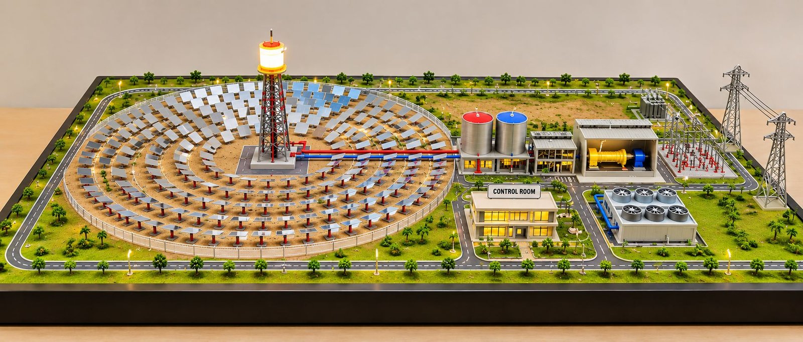
A Concentrated Solar Power Plant Model represents an advanced renewable energy facility that uses mirrors to collect and concentrate sunlight for electricity generation. This engineering model demonstrates how a large number of solar reflectors direct sunlight toward a central receiver, produce high-temperature heat and operate a power generation system. It combines solar technology, mechanical equipment, thermal energy storage and electrical infrastructure in one detailed physical presentation.
Renewable energy plays an important role in modern electricity production. As industries, commercial buildings and infrastructure projects require more power, engineers continue to explore different ways to generate clean electricity. Solar photovoltaic panels already provide electricity to millions of installations. However, concentrated solar power technology offers another approach by using sunlight to produce and store thermal energy.
Unlike conventional solar panels, a concentrated solar power system uses mirrors or reflectors to focus sunlight onto a receiver. The receiver transfers the collected solar energy into heat. This heat can produce steam, operate a turbine and drive an electrical generator.
A detailed physical model brings together several important components, including a heliostat field, central solar tower, receiver, thermal storage tanks, heat exchangers, steam turbine, generator, cooling equipment and electrical substation.
Moreover, the model can include a control building, maintenance roads, pipelines, transformers and transmission towers. These elements help explain how the different sections work together inside a complete solar power facility.
A professionally developed Concentrated Solar Power Plant Model helps engineering students, technical institutions, renewable energy companies and project developers understand the complete plant arrangement. It also provides a useful visual presentation for technical exhibitions, educational demonstrations and infrastructure project proposals.
What Is Concentrated Solar Power Technology?
Concentrated Solar Power (CSP) is a renewable energy technology that uses mirrors to concentrate direct sunlight onto a specific receiver. The receiver collects the solar energy and converts it into high-temperature thermal energy.
Engineers use this heat to produce steam or operate other suitable power conversion systems. The resulting mechanical energy drives a generator and produces electricity.
Unlike photovoltaic technology, which converts sunlight directly into electrical energy, CSP technology first converts sunlight into heat.
This difference makes thermal energy storage an important feature of many concentrated solar power facilities. For example, certain plants store heat in molten salt and use it later when sunlight becomes unavailable.
Solar Energy Collection System
The solar collection system contains mirrors or reflectors that capture direct sunlight.
These reflectors follow the Sun’s position and direct solar radiation toward the receiver. Therefore, their alignment and tracking arrangement play an important role in the overall system.
Thermal Energy Conversion
The receiver absorbs concentrated sunlight and transfers the energy into a suitable heat transfer medium.
Depending on the plant design, this medium may include molten salt, thermal oil, water or another suitable working fluid.
The heated medium then transfers thermal energy to the power generation system or storage equipment.
Electricity Generation System
The power block converts collected thermal energy into mechanical and electrical energy.
In a conventional steam-based CSP plant, a steam generator produces high-pressure steam. This steam drives a turbine connected to an electrical generator.
Finally, transformers and electrical equipment transfer the generated electricity toward the grid.
Overall Design of a Concentrated Solar Power Plant Model
The overall design of a concentrated solar power plant model should represent the complete relationship between the solar collection area, thermal processing equipment and electrical generation infrastructure.
A wide rectangular layout provides sufficient space for the heliostat field, central receiver tower, storage tanks, powerhouse and electrical substation.
The solar reflector field generally occupies a large section of the baseboard. Meanwhile, the central tower provides the main visual focus of the engineering model.
The thermal storage and power generation equipment can occupy a separate industrial section. In addition, the electrical substation and transmission towers complete the overall infrastructure arrangement.
Main Structural Arrangement of the CSP Model
The heliostat field forms the main solar collection area. It consists of numerous miniature mirror assemblies arranged around the central receiver tower.
Each reflector has a support structure and tracking mechanism. These elements help demonstrate how the mirrors direct sunlight toward the receiver.
The central solar tower contains the receiver at its upper section. Below it, the model can show supporting columns, access platforms, maintenance ladders and structural foundations.
The thermal storage area contains insulated storage tanks and connecting pipelines. Furthermore, the powerhouse includes the steam turbine, generator and related equipment.
A control building can stand near the main industrial facilities. Its windows, service entrance and surrounding access road provide additional physical detailing.
The complete model should maintain clear visibility of all major engineering components without unnecessary signs, floating labels or decorative arrows.
Major Components of a Concentrated Solar Power Plant Model
A concentrated solar power facility contains several connected systems. Each component performs a specific function during solar energy collection, thermal conversion and electricity production.
Heliostat Field System
The heliostat field is one of the most important sections of a solar tower power plant.
It consists of many movable mirrors called heliostats. These mirrors follow the Sun and reflect sunlight toward a receiver located on top of a central tower.
Each heliostat generally includes a reflective surface, support frame, foundation and tracking mechanism.
A detailed physical model should show multiple mirror assemblies arranged in a planned field pattern.
Important heliostat components include:
- Reflective mirror panels
- Steel support frames
- Tracking mechanisms
- Rotating joints
- Foundation supports
- Motor assemblies
- Mirror mounting brackets
- Electrical control connections
The mirror field should have a realistic arrangement and consistent spacing. Moreover, each mirror should face the central receiver in a way that makes the solar collection concept easy to understand.
Heliostat Tracking Mechanism
Heliostats use tracking systems to maintain the correct mirror orientation throughout the day.
These systems generally adjust the mirror position along two axes. As a result, the reflectors can direct sunlight toward the receiver as the Sun moves across the sky.
A miniature physical representation can include small rotating supports, motor housings and metal brackets.
Central Solar Receiver Tower
The central solar tower receives concentrated sunlight from the surrounding heliostat field.
Its upper section contains the receiver assembly, where the reflected solar radiation produces high temperatures.
The tower requires a strong structural arrangement because it supports the receiver and related equipment.
A physical model can include:
- Steel tower framework
- Receiver housing
- Support columns
- Maintenance platforms
- Access ladders
- Safety railings
- Equipment supports
- Foundation structure
The receiver should remain clearly visible at the top of the tower.
Solar Receiver Assembly
The receiver absorbs concentrated sunlight and transfers the heat to a working fluid.
Different receiver designs use different arrangements of tubes, panels and heat transfer passages.
The model can represent the receiver as a compact industrial assembly with metallic surfaces, connecting pipes and support frames.
Thermal Energy Storage System
Thermal energy storage allows certain CSP plants to retain collected heat and use it later.
Molten salt is a common storage medium in suitable solar tower systems.
The system generally uses insulated tanks to store hot and cold salt at different temperatures.
When the plant needs additional heat for electricity generation, the stored thermal energy passes through a suitable heat transfer arrangement.
A detailed model should include separate storage tanks, connecting pipelines, valves and support foundations.
Molten Salt Storage Tanks
Molten salt storage tanks form an important part of many tower-based CSP facilities.
The hot tank stores heated salt from the solar receiver. Meanwhile, the cold tank stores salt that has transferred its thermal energy through the power generation process.
The model can show two large cylindrical tanks with insulated outer surfaces, connecting pipes and access platforms.
Heat Exchanger System
Heat exchangers transfer thermal energy between different fluids.
In a molten salt CSP plant, the system can transfer heat from the storage medium to water or another working fluid.
This process supports steam production for the turbine system.
The physical model can include miniature heat exchanger vessels, connecting pipelines, valves and equipment foundations.
These details help explain the relationship between thermal storage and the power block.
Steam Generator System
The steam generator uses thermal energy to convert water into high-pressure steam.
The steam then enters the turbine and produces rotational mechanical energy.
A realistic physical model can represent the steam generator as an industrial vessel with connecting pipes, support frames and insulation.
In addition, the water supply and steam outlet connections should remain visible.
Steam Turbine Assembly
The steam turbine converts the energy of high-pressure steam into mechanical rotational energy.
Steam enters the turbine and passes through a series of blades mounted on a rotating shaft.
This movement drives the generator and produces electricity.
A detailed turbine assembly can include:
- Turbine casing
- Rotor shaft
- Turbine blade stages
- Bearing supports
- Steam inlet connection
- Exhaust section
- Mechanical coupling
- Foundation frame
The turbine should appear as a separate industrial machine rather than a simple decorative building.
Electrical Generator
The generator converts mechanical energy from the rotating turbine into electrical energy.
The turbine shaft transfers rotational movement to the generator rotor. Electromagnetic induction then produces electrical power inside the machine.
A detailed physical model should show the generator housing, shaft connection, support structure and electrical terminals.
Furthermore, the generator should connect logically with the transformer and electrical distribution equipment.
Condenser and Cooling System
After steam passes through the turbine, the condenser converts the exhaust steam back into water.
This process allows the plant to reuse water within the steam cycle.
A cooling system removes heat from the condenser. Depending on the plant design, this system may use cooling towers, air-cooled condensers or other cooling arrangements.
The model can include cooling fans, condenser equipment, water pipes and support structures.
Transformer and Electrical Substation
The generator produces electrical power, but the plant also requires electrical equipment to prepare that power for transmission.
A transformer adjusts the voltage according to grid requirements.
The substation contains equipment for switching, protection and electrical control.
Important components include:
- Power transformer
- High-voltage bushings
- Circuit breakers
- Isolators
- Busbars
- Electrical insulators
- Protection equipment
- Cable connections
A miniature electrical substation completes the power generation section of the model.
Power Transmission Towers
Transmission towers carry electricity from the solar power facility toward the electrical grid.
The model can include lattice steel towers, cross-arms, insulators and overhead conductors.
These structures should connect visually with the electrical substation.
Consequently, viewers can understand how electricity travels from the generator to the wider power network.
Control Room and Monitoring Building
The control room monitors the operation of the concentrated solar power plant.
Modern facilities use monitoring systems to manage heliostat positions, receiver temperatures, storage conditions, turbine operation and electrical output.
A miniature control building can include glazed windows, an entrance, internal lighting and a realistic roof structure.
Moreover, the control building should sit naturally within the industrial layout rather than appearing as a separate display board.
Working Principle of a Concentrated Solar Power Plant
The working principle of a concentrated solar power plant involves several connected stages.
First, the mirrors collect direct sunlight. Next, the receiver converts solar radiation into heat. After that, the thermal system transfers energy to the power block. Finally, the turbine and generator produce electricity.
Solar Radiation Collection
The process begins when sunlight reaches the heliostat field.
Each mirror follows the Sun and reflects the incoming radiation toward the central receiver.
The combined reflected energy produces a high-temperature heat source.
Heat Absorption in the Solar Receiver
The receiver absorbs the concentrated solar radiation.
A suitable heat transfer fluid moves through the receiver and collects thermal energy.
Depending on the plant design, the fluid may include molten salt or another suitable medium.
Thermal Energy Storage
Some concentrated solar power facilities store the collected heat for later use.
The hot heat transfer medium enters the storage system and retains thermal energy inside insulated tanks.
Therefore, the plant can continue producing electricity for a period when sunlight becomes unavailable, subject to its storage capacity and operating conditions.
Steam Production
The thermal system transfers heat to water through a steam generator or heat exchanger.
The water reaches the required operating conditions and produces high-pressure steam.
This steam then enters the turbine.
Mechanical Energy Conversion
High-pressure steam passes through the turbine blades and causes the rotor shaft to rotate.
The turbine converts thermal energy into mechanical energy.
The connected generator receives this rotational movement and produces electricity.
Electrical Power Generation and Transmission
The generator supplies electrical power to the plant’s electrical system.
Next, the transformer adjusts the voltage for transmission.
Finally, the substation and transmission towers connect the plant with the electrical grid.
Thus, the complete process converts concentrated sunlight into usable electrical energy.
Different Types of Concentrated Solar Power Systems
Concentrated solar power technology uses different reflector and receiver arrangements.
Each technology has its own engineering design and operating characteristics.
Solar Power Tower System
A solar power tower uses a large field of heliostats to reflect sunlight toward a central receiver.
The receiver sits at the top of a tower and collects concentrated solar energy.
This system can operate with suitable thermal storage technology, including molten salt.
A solar tower model is especially useful for demonstrating a large heliostat field, central receiver and industrial power block.
Parabolic Trough Solar System
A parabolic trough system uses curved mirrors to focus sunlight onto a receiver tube positioned along the mirror’s focal line.
A heat transfer fluid flows through the receiver tube and collects solar energy.
The heated fluid then supplies thermal energy to a steam generation system.
A physical model can include multiple rows of curved reflector assemblies and long receiver tubes.
Linear Fresnel Reflector System
A linear Fresnel system uses several rows of long, narrow mirrors to focus sunlight onto a fixed elevated receiver.
The mirrors follow the Sun and direct radiation toward the receiver.
This arrangement uses a different reflector layout from a parabolic trough system.
A model can show parallel mirror rows, receiver supports and the connecting thermal equipment.
Parabolic Dish Solar System
A parabolic dish system uses a dish-shaped reflector to concentrate sunlight onto a receiver positioned near its focal point.
Some systems connect the receiver to a Stirling engine or another suitable power conversion device.
The model can show the dish structure, support frame, tracking arrangement and power conversion equipment.
Engineering Disciplines Involved in CSP Plant Development
Developing a concentrated solar power facility requires coordination between several engineering disciplines.
Civil and Structural Engineering
Civil engineers design the plant foundations, equipment platforms, tower structures, roads and buildings.
Structural engineers consider equipment loads, wind forces, thermal conditions and foundation requirements.
The physical model can demonstrate these elements through concrete foundations, steel structures and supporting platforms.
Mechanical Engineering
Mechanical engineers work on turbines, generators, pumps, heat exchangers, storage tanks and piping systems.
They also consider the thermal performance and mechanical reliability of the plant.
The equipment arrangement should clearly show the connection between the solar receiver, storage system and power block.
Electrical Engineering
Electrical engineers design generator connections, transformers, switchgear, protection systems and transmission infrastructure.
They also develop the electrical control arrangements required for safe plant operation.
Thermal Engineering
Thermal engineering plays an important role in CSP development.
Engineers study heat transfer, fluid movement, storage temperature, steam generation and thermal losses.
These processes determine how effectively the plant converts collected solar energy into useful power.
Instrumentation and Control Engineering
Instrumentation engineers monitor heliostat tracking, receiver temperature, fluid flow, storage conditions and generator output.
Automated control systems help coordinate different plant operations.
Consequently, the monitoring system supports efficient and reliable power generation.
Physical Scale Model Making for Concentrated Solar Power Projects
A professional Concentrated Solar Power Plant Model requires careful planning, realistic proportions and visible equipment detailing.
The objective is to represent the complete facility as a physical engineering model rather than a simple decorative display.
Baseboard and Overall Layout
The baseboard provides the foundation for all model components.
A wide rectangular baseboard works well because the solar reflector field occupies a large area, while the receiver tower and power block require separate sections.
The heliostat field should remain the main visual feature. Meanwhile, the thermal storage tanks and powerhouse should have sufficient space for clear equipment placement.
A clean baseboard with properly finished edges improves the overall presentation.
Solar Mirror Fabrication
The heliostat mirrors require consistent shapes, suitable reflective surfaces and accurate support arrangements.
Model makers can use reflective acrylic or other suitable materials to create miniature mirror panels.
Each reflector should have a visible support frame and mounting assembly.
Moreover, the mirror field should maintain an organized pattern around the central tower.
Receiver Tower Construction
The central tower requires a strong-looking support structure and a visible receiver assembly.
Model makers can use acrylic, PVC sheets, metal sections and fabricated structural components to create the tower.
The receiver should remain clearly visible at the top. In addition, access platforms, ladders and support frames improve the engineering appearance.
Thermal Storage and Piping Detailing
The storage area should include cylindrical tanks, connecting pipes, valves and equipment foundations.
Different pipe finishes can distinguish hot and cold thermal fluid lines.
Furthermore, small pipe supports, flanges and industrial fittings improve the physical appearance.
Powerhouse and Turbine Equipment
The powerhouse should include visible turbine and generator equipment.
An open section or suitable cutaway arrangement can reveal the machinery without hiding the main building structure.
The model can also include heat exchangers, steam generator vessels, pumps and supporting frames.
Electrical Infrastructure
The electrical area can feature transformers, switchgear, insulators, cable connections and transmission towers.
These components help communicate the complete power generation and distribution arrangement.
Landscaping and Presentation
The surrounding area can include access roads, small trees, grass sections, boundary fencing and utility pathways.
However, landscaping should not cover the main engineering equipment.
Miniature lighting can highlight selected structures and buildings. At the same time, the model should maintain clear visibility of the solar reflectors, receiver and industrial machinery.
Materials and Techniques Used in CSP Engineering Model Making
Material selection depends on the project size, technical requirements and required presentation quality.
Different fabrication methods support different parts of the model.
Acrylic and Reflective Materials
Acrylic sheets work well for buildings, transparent panels and selected structural elements.
Reflective materials can represent the heliostat mirrors and create a realistic solar collection field.
PVC and Foam-Based Materials
PVC sheets and foam-based materials help create lightweight buildings, walls, foundations and equipment enclosures.
Model makers can cut and shape these materials according to the required dimensions.
3D Printed Components
3D printing helps create complex components such as turbine housings, receiver parts, equipment covers, pipe fittings and miniature mechanical assemblies.
Moreover, this technique supports accurate production of repeated or custom-shaped components.
Laser Cutting and Precision Fabrication
Laser cutting helps produce accurate structural panels, mirror supports, building components and equipment platforms.
It also provides consistent dimensions and clean edges.
Metal and Resin Components
Metal sections can represent support structures, ladders, railings and industrial frames.
Resin components can provide detailed shapes for machinery and specialized equipment.
Combining these materials helps create a realistic physical engineering presentation.
Applications of Concentrated Solar Power Plant Models
CSP models support several educational, industrial and professional applications.
Engineering College Projects
Engineering students can use concentrated solar power models to understand solar thermal technology, heat transfer, turbine operation and electricity generation.
These models also provide a practical way to explain renewable energy concepts during academic presentations.
Renewable Energy Exhibitions
Renewable energy exhibitions bring different clean energy technologies together.
A detailed CSP model helps visitors understand how mirrors collect sunlight and convert it into electricity.
Furthermore, it provides a visual comparison with solar photovoltaic and wind energy systems.
Industrial Project Presentations
Renewable energy companies and engineering consultants can use physical models to present proposed solar thermal facilities.
The model helps clients understand the heliostat field, central receiver, storage tanks and power block.
Research and Technical Demonstrations
Research institutions can use CSP models to explain solar collection systems, thermal storage and power generation processes.
Similarly, technical demonstrations can communicate complex engineering information to a wider audience.
Corporate and Infrastructure Displays
Companies working in renewable energy, power generation and industrial infrastructure can use customized models for exhibitions, technical meetings and corporate presentations.
Advantages of Concentrated Solar Power Technology
Concentrated solar power offers several useful characteristics for renewable electricity production.
Thermal Energy Storage
One important advantage of suitable CSP systems is the ability to store thermal energy.
For example, molten salt storage can retain heat and supply it to the power block after direct sunlight decreases.
Therefore, the system can support electricity generation beyond periods of strong sunshine.
Renewable Energy Source
CSP uses sunlight as its primary energy source.
Unlike conventional fossil-fuel power plants, the solar collection process does not require continuous fuel combustion.
Large-Scale Power Generation
CSP technology can support utility-scale electricity generation.
Large reflector fields and industrial power blocks allow engineers to design facilities for significant power output.
Flexible Power Generation
Thermal storage can provide greater flexibility in electricity generation.
However, the actual operating duration depends on storage capacity, plant design and available solar energy.
Reduced Direct Operational Emissions
CSP electricity generation does not involve direct fossil-fuel combustion during normal solar operation.
As a result, it can contribute to lower operational greenhouse gas emissions compared with conventional fossil-fuel generation.
Challenges in Concentrated Solar Power Plant Development
Although CSP offers several advantages, engineers must consider important technical and environmental challenges.
High Initial Construction Cost
A concentrated solar power facility requires a large heliostat field, receiver tower, thermal equipment, storage tanks and power generation infrastructure.
Consequently, initial construction costs can be significant.
Land Requirements
Large solar tower facilities require substantial land for the reflector field.
Engineers must consider site conditions, access roads, terrain and suitable sunlight availability before selecting a location.
Water Requirements
Some CSP plants use water for cooling and steam cycle operations.
Therefore, water availability becomes an important planning factor, particularly in dry regions.
Air-cooled systems can reduce cooling water requirements, although they involve different performance and cost considerations.
Mirror Cleaning and Maintenance
Dust and dirt can reduce the reflective performance of heliostat mirrors.
For this reason, plants require suitable cleaning systems and regular inspection.
Thermal Equipment Management
High operating temperatures place demands on receivers, pipes, valves, storage tanks and heat exchangers.
Engineers must select suitable materials and develop proper maintenance procedures.
Difference Between Concentrated Solar Power and Solar Photovoltaic Systems
Both technologies use sunlight to produce electricity. However, their energy conversion methods are different.
Concentrated Solar Power
CSP uses mirrors to focus sunlight onto a receiver.
The receiver produces thermal energy, which supports a turbine or another power conversion system.
In addition, suitable CSP facilities can store thermal energy for later electricity production.
Solar Photovoltaic Technology
Solar photovoltaic panels convert sunlight directly into electrical energy through semiconductor materials.
They do not require a thermal receiver, steam turbine or molten salt storage system for basic electricity generation.
Therefore, the physical model of a CSP plant should clearly show its mirrors, receiver tower, thermal equipment and power block.
Modern Technologies Used in Concentrated Solar Power Plants
Engineering improvements continue to support the development of solar thermal power systems.
Advanced Heliostat Tracking
Modern tracking systems help maintain accurate mirror positions throughout the day.
Better control can improve the collection of direct solar radiation.
High-Temperature Receiver Technology
Receiver technology plays an important role in thermal energy collection.
Engineers continue to study materials and designs that can operate under high temperatures and demanding environmental conditions.
Advanced Thermal Storage
Thermal storage research focuses on improving energy retention, heat transfer and system performance.
Molten salt remains an established option in suitable commercial CSP facilities.
Automated Plant Monitoring
Modern monitoring systems collect information from heliostats, receivers, storage tanks, turbines and electrical equipment.
Consequently, operators can observe different plant conditions and plan maintenance more effectively.
Digital Engineering and Simulation
Digital tools help engineers study solar radiation, mirror alignment, thermal performance and mechanical systems.
A physical scale model complements these tools by showing the overall plant arrangement in a clear three-dimensional format.
Professional Presentation of a Concentrated Solar Power Plant Model
A professional engineering model should communicate the complete facility without unnecessary visual elements.
The heliostat field and central receiver tower should remain the main focus. At the same time, the thermal storage tanks and powerhouse equipment should remain clearly visible.
The industrial section should show a logical connection between the receiver, storage system, steam generator and turbine.
Realistic mirror surfaces, structural supports, pipelines, machinery and electrical equipment improve the presentation.
A suitable control building can stand within the industrial area, while access roads and landscaping provide environmental context.
Moreover, the entire arrangement should fit naturally on one wide rectangular baseboard.
The final design should reflect the technical drawings, project requirements and intended presentation purpose.
Importance of Professional Engineering Scale Model Making
Engineering scale models help communicate complex industrial facilities through physical three-dimensional representations.
Technical drawings explain dimensions and equipment layouts. However, a physical model makes it easier to understand how different structures and systems connect.
This becomes particularly useful for concentrated solar power projects because they combine solar reflectors, thermal equipment, mechanical machinery and electrical infrastructure.
A professionally developed CSP model brings these different systems together in one presentation.
Accurate proportions, visible machinery, realistic finishes and clear equipment placement all contribute to the final result.
Therefore, professional engineering model making plays an important role in technical presentations, renewable energy exhibitions and infrastructure project visualization.
PAL Design Models – Industrial and Engineering Scale Model Making
PAL Design Models provides customized industrial and engineering scale model-making services for technical presentations, infrastructure projects, exhibitions and project visualization.
Industrial and renewable energy facilities often contain complex equipment and interconnected systems. Physical models help present these arrangements in a way that clients, engineers and other stakeholders can understand.
A concentrated solar power plant model involves several technical elements, including heliostat fields, solar receiver towers, thermal storage tanks, steam turbines, generators and electrical transmission infrastructure.
PAL Design Models can develop customized physical representations according to project drawings, dimensions, technical requirements and presentation objectives.
The company’s model-making service categories include:
- Industrial Model Making
- Engineering Model Making
- Power Plant Scale Models
- Solar Power Plant Models
- Renewable Energy Models
- Mechanical Engineering Models
- Electrical Engineering Models
- Marine Engineering Models
- Industrial Plant Models
- Infrastructure Scale Models
- Architectural Model Making
- 3D Printing Services
- Laser Cutting Services
Each project requires a suitable approach to structural design, component fabrication and final presentation.
For more information about customized engineering and industrial model-making services, visit the official website.
Website: https://paldesignmodels.com/
Conclusion
A Concentrated Solar Power Plant Model provides a detailed three-dimensional representation of how concentrated sunlight can generate electrical power.
The model combines several important engineering systems, including heliostat mirrors, central receiver towers, thermal storage tanks, heat exchangers, steam generators, turbines, electrical generators and transmission infrastructure.
Each component contributes to the complete energy conversion process. Together, these systems demonstrate how sunlight becomes thermal energy, how thermal energy drives mechanical equipment and how generators produce electricity.
A professional physical model also helps explain the relationship between solar collection and industrial power generation equipment.
Careful planning, accurate proportions, visible mirror assemblies, realistic receiver structures and detailed mechanical equipment improve the quality of the final presentation.
As renewable energy development continues, concentrated solar power remains an important subject for engineering education, technical research and industrial infrastructure planning.
Ultimately, a well-designed physical scale model makes this technology easier to understand and provides a valuable presentation tool for engineering students, professionals, project developers and renewable energy organizations.