Advanced Thermal Power Plant Engineering Model: Power Generation, Cooling, Transformation & Transmission System
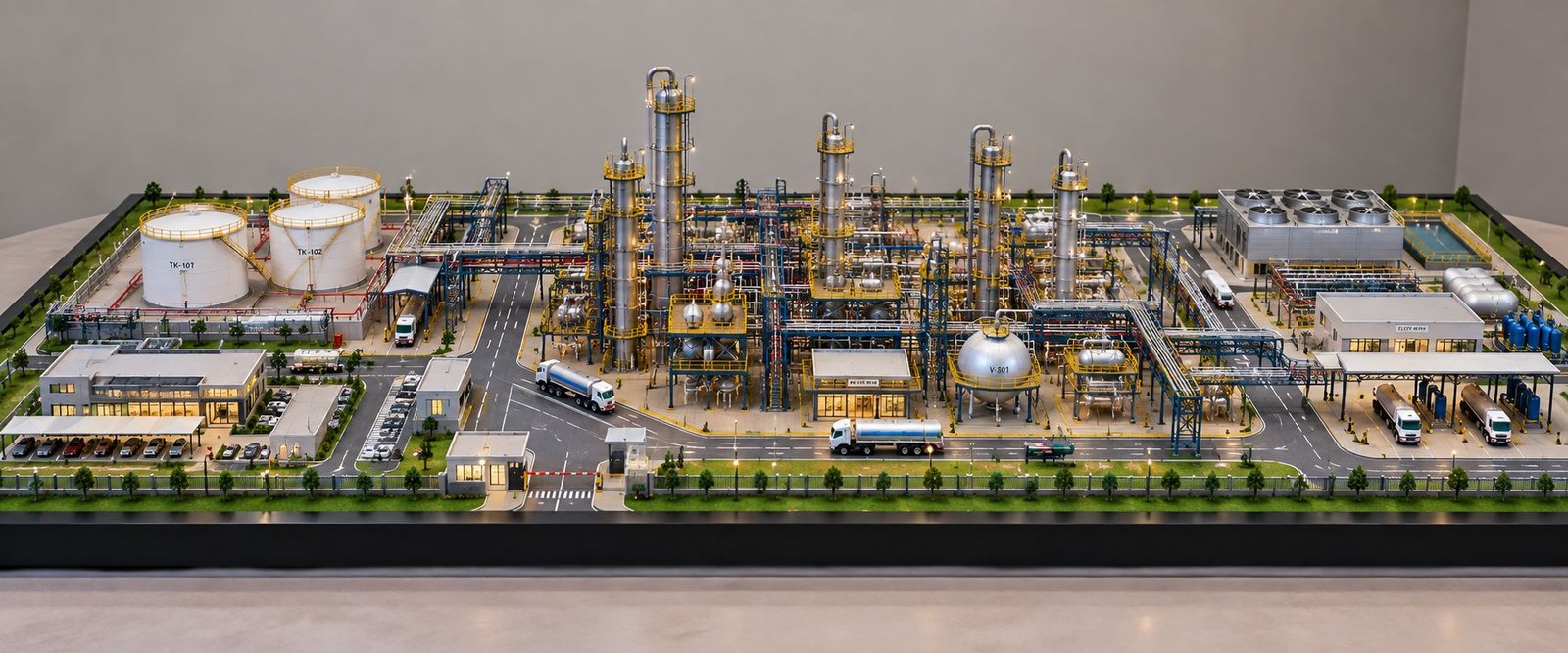
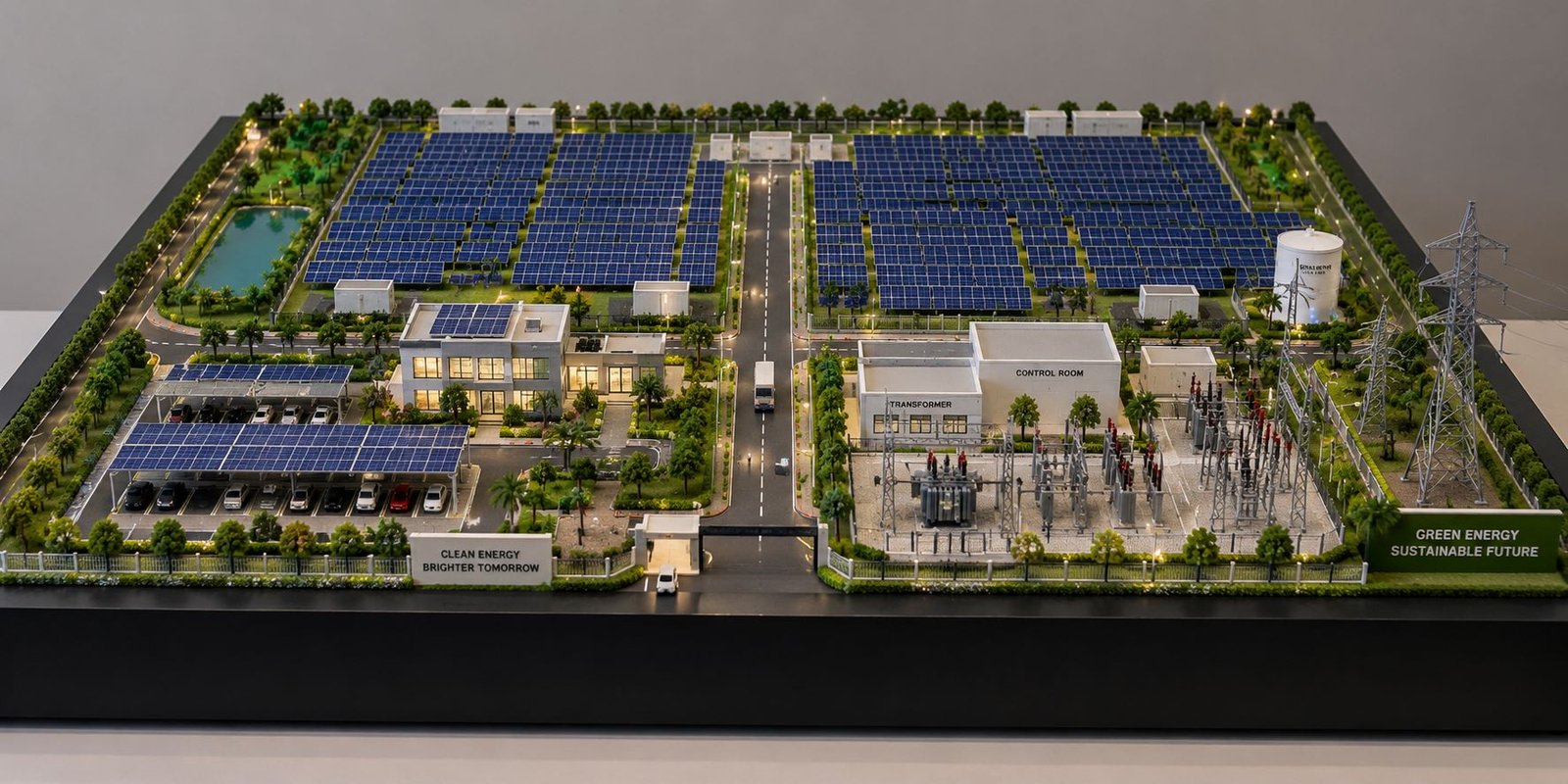
A Thermal Power Plant Engineering Model is an advanced engineering demonstration that represents the complete journey of electricity from fuel combustion to high-voltage transmission. The model shown here has been designed as a detailed physical scale model. In addition, it integrates the coal handling system, boiler house, steam turbine-generator section, cooling towers, condenser and water circuit, electrical switchyard, transformers, transmission towers and supporting plant infrastructure into one systematic layout.
The purpose of such a model is not simply to show what a thermal power station looks like. Instead, its real value is to explain how different thermal, mechanical and electrical systems work together to generate and transmit electrical power.
Understanding the Complete Thermal Power Generation System
A conventional steam-based thermal power plant works through a sequence of energy conversions. Therefore, the complete process can be understood as:
Chemical Energy → Thermal Energy → Steam Energy → Mechanical Energy → Electrical Energy → Transmitted Electrical Power
The complete process represented by this engineering model can be understood through four interconnected systems:
1. Fuel & Thermal System
Coal → Combustion → Boiler → Steam
2. Mechanical System
Steam → Turbine → Shaft Rotation
3. Electrical System
Generator → Transformer → Switchyard
4. Transmission System
Switchyard → High-Voltage Transmission → Grid
Alongside these systems, the condenser and cooling-water system continuously remove waste heat and support the steam cycle.
1. Coal Handling and Fuel Preparation
The first stage of the power plant is the coal handling system. Coal stays in the designated storage area and then moves toward the boiler through mechanical handling equipment. Therefore, this stage provides the fuel needed for continuous thermal generation.
In an actual plant, coal handling can involve:
Coal receiving system
Storage yard
Conveyors
Crushers
Transfer points
Feeders
Pulverizing equipment
Controlled fuel supply
The engineering model represents this stage as the starting point of the thermal generation process.
Energy Flow
Coal → Fuel Preparation → Combustion System
For this reason, the plant must maintain a consistent fuel supply because the boiler needs continuous fuel to maintain steam production.
2. Boiler and Combustion System
The boiler system forms the thermal heart of the power plant.
Inside the boiler furnace, fuel combustion produces a large amount of heat. This thermal energy moves to water through heat-transfer surfaces and produces high-pressure and high-temperature steam. As a result, the boiler converts the heat from fuel into useful steam energy.
The simplified process is:
Fuel Combustion → Heat Transfer → Water Heating → Steam Generation
An advanced thermal power plant may contain several heat-transfer sections such as economizers, evaporator/water-wall sections, superheaters and reheaters. In addition, these sections help the plant manage the heating process at different stages.
Therefore, the boiler area in a professional power plant working model looks like a complex industrial structure rather than a simple box.
3. Superheated Steam and Steam Turbine
The boiler sends the steam toward the steam turbine. Next, the turbine uses the energy stored in the steam to produce mechanical rotation.
In a large steam power station, turbine sections may include:
High-pressure turbine
Intermediate-pressure turbine
Low-pressure turbine
As steam expands through the turbine stages, its pressure and temperature decrease. At the same time, the steam transfers its energy to the turbine rotor.
The turbine converts:
Steam Energy → Mechanical Rotational Energy
Next, the turbine shaft connects to the generator and creates the mechanical-to-electrical energy conversion stage.
4. Generator and Electrical Power Production
The generator converts the mechanical rotation from the turbine into electrical energy.
The basic principle is electromagnetic induction. When the turbine rotates the generator shaft, the generator produces electrical power. Therefore, the generator forms the key link between the mechanical and electrical systems.
The central conversion chain of the model is:
Boiler → Steam → Turbine → Generator → Electricity
As a result, this is one of the most important concepts demonstrated by a Thermal Power Plant Working Model.
5. Condenser: Completing the Steam Cycle
After the steam passes through the turbine, the low-pressure exhaust steam must change back into water.
The condenser performs this process.
Cooling water flows through the condenser and removes heat from the turbine exhaust steam. As a result, the steam condenses into water. The system can then pump this water back toward the boiler.
The complete cycle becomes:
Boiler → Turbine → Condenser → Feedwater System → Boiler
Therefore, this continuous circulation creates a closed thermodynamic cycle rather than a one-way process.
6. Cooling Tower and Heat-Rejection System
The large cooling towers are one of the most recognizable structures in the model.
Their engineering purpose is to reject unwanted heat from the cooling-water circuit. In this way, the cooling system supports the overall thermal cycle.
The cooling-water system can be represented as:
Condenser → Warm Water → Cooling Tower → Heat Rejection → Cooled Water → Condenser
Therefore, the cooling tower does not directly generate electricity. Instead, it supports the thermal cycle by allowing the condenser to operate effectively.
The model’s cooling towers, water infrastructure and surrounding plant structures visually demonstrate this important heat-management system. In addition, they help explain how the plant handles excess heat.
7. Water Management and Auxiliary Systems
Water is an important resource throughout a thermal power station.
It can be associated with:
Steam generation
Condensation
Cooling
Boiler feedwater
Heat rejection
Auxiliary plant requirements
The model incorporates a visible water channel and plant-side water infrastructure to represent this part of the engineering system.
In addition, a more advanced working model can integrate water-flow indicators or miniature pumps to demonstrate the relationship between the steam cycle and cooling circuit.
8. Generator Transformer and Voltage Step-Up
The electricity produced by the generator does not normally travel over long distances at the generator’s voltage level.
Instead, the output connects to a generator step-up transformer, which raises the voltage to a suitable transmission level.
This is an important electrical engineering principle because, for a given transmitted power, increasing voltage allows current to decrease. As a result, lower current reduces resistive losses in the transmission conductors.
The model therefore represents an important transition:
Generator Output → Step-Up Transformer → Switchyard
9. High-Voltage Switchyard
The switchyard forms the electrical control and connection zone between the generating station and the transmission network.
The detailed electrical yard in the model represents equipment such as:
Busbars
Circuit breakers
Isolators
Instrument transformers
Surge protection
Power transformers
Transmission connections
The switchyard allows operators to control and isolate electrical circuits and connect them to the appropriate transmission paths. Therefore, it plays an important role in the safe operation of the electrical system.
For this reason, the switchyard becomes one of the most technically important sections of the entire model.
10. Transmission Towers and Power Grid Connection
After voltage transformation and switchyard operations, electrical power moves into the high-voltage transmission network.
The miniature transmission towers and overhead conductors shown in the model represent the infrastructure required to transfer bulk electrical power over long distances. Therefore, this section demonstrates the final stage of the power transmission process.
The complete electrical pathway is:
Generator → Step-Up Transformer → Switchyard → Transmission Line → Grid
From the transmission grid, electricity can ultimately reach distribution substations and then different categories of consumers. As a result, the model connects power generation with the wider electrical grid.
11. Control, Protection and Plant Auxiliary Infrastructure
A modern power station cannot operate using only the boiler, turbine and generator.
In addition, supporting systems are required for:
Electrical protection
Instrumentation
Monitoring
Plant control
Water treatment
Equipment cooling
Fire protection
Internal power supply
Maintenance
Communication and safety
The supporting buildings and electrical infrastructure shown in the model help represent this wider balance-of-plant system.
Therefore, these systems give an advanced engineering model a realistic industrial character.
Complete Working Sequence
The entire model can be explained through the following engineering sequence. Together, these stages show how the different plant systems operate as one complete system.
Thermal Energy Path
Coal Storage → Coal Handling → Boiler → Steam Generation → Superheated Steam
Mechanical Energy Path
Steam → Turbine Expansion → Turbine Shaft → Generator
Electrical Energy Path
Generator → Step-Up Transformer → Switchyard → High-Voltage Transmission Line
Steam Recovery Path
Turbine Exhaust → Condenser → Condensate → Feedwater System → Boiler
Cooling Path
Condenser → Warm Cooling Water → Cooling Tower → Heat Rejection → Cooled Water → Condenser
Finally, these paths create an integrated representation of a thermal power generation system.
What Makes This Model an Advanced Engineering Project?
A basic power plant model generally shows only a chimney, turbine and generator. However, an advanced Thermal Power Plant Project Model goes much further by representing the relationship between multiple engineering disciplines.
Thermal Engineering
Boiler, combustion, steam generation and heat transfer.
Mechanical Engineering
Steam turbine, rotating shaft, condenser and auxiliary mechanical systems.
Electrical Engineering
Generator, transformer, switchgear, busbars and protection equipment.
Power System Engineering
Switchyard, high-voltage transmission lines and grid connectivity.
Civil & Infrastructure Engineering
Industrial buildings, roads, water channels, foundations and plant layout.
As a result, this multidisciplinary integration makes the model suitable for technical exhibitions and advanced educational demonstrations.
Professional Detailing in the Physical Model
The visual quality of an engineering model depends heavily on scale, proportion, component placement and finishing.
For a professional engineering model making project, elements such as miniature steel structures, electrical equipment, cooling towers, industrial buildings, pipelines, transmission pylons, landscaping and internal roads should follow a logical plant layout.
In addition, modern fabrication techniques can improve such projects. Laser cutting can produce accurate structural panels and equipment components, while 3D printing can create customized miniature machinery, transformers, turbine components, tanks and architectural details.
As a result, this combination of precision fabrication and detailed finishing can transform a conventional science project into a professional industrial scale model.
Interactive Working Model Possibilities
The model can become an advanced demonstration system by integrating electronics and controlled motion.
Possible features include:
Sequential LED power-flow indication
Rotating miniature turbine
Illuminated switchyard
Working cooling-tower effect
Pump-driven water circulation
Interactive control switches
Generator demonstration
Automatic operating sequence
Separate thermal and electrical flow indicators
For an exhibition, a simple control interface can allow the viewer to activate different sections and understand the relationship between generation, transformation, cooling and transmission.
Applications of the Thermal Power Plant Model
This type of advanced model can be developed for:
Electrical Engineering Projects
Mechanical Engineering Projects
Diploma Engineering Exhibitions
Engineering College Projects
School Science Exhibitions
Industrial Training Models
Power Generation Demonstrations
STEM Education
Technical Presentations
Corporate and Industrial Displays
Engineering Exhibition Projects
In addition, for institutions in Delhi NCR and other major Indian education and industrial hubs, a professionally fabricated model can also be customized according to available display space, required scale, working features and presentation requirements.
Final Conclusion
This Advanced Thermal Power Plant Engineering Model represents much more than the physical appearance of a power station. It demonstrates the complete engineering relationship between fuel handling, combustion, boiler operation, steam generation, turbine expansion, generator operation, condensation, cooling, voltage transformation, switchyard control and high-voltage transmission.
The model effectively connects thermal engineering, mechanical engineering and electrical power-system engineering into one physical demonstration.
Its systematic layout makes it possible to explain the complete journey:
Fuel → Heat → Steam → Turbine → Generator → Transformer → Switchyard → Transmission Grid
At the same time, the condenser and cooling-tower system complete the thermal cycle:
Turbine → Condenser → Cooling System → Feedwater → Boiler
Finally, with precision fabrication, detailed miniature components, laser-cut structures, 3D-printed engineering parts, realistic electrical equipment and optional interactive electronics, this concept can become a professional-grade Thermal Power Plant Working Model and Engineering Exhibition Model suitable for advanced technical presentations and educational demonstrations.